CYCLONE-User-Manual.pdf - 第63页
User Manual For Cyclone LC Programmers 63 7 CYCLONE PROGRAMMER MANUAL CONTROL The Cyclone LC must be configured before it can serve as a Stand-Alone Programmer . The user may manually control the Cyclone via the LCD touc…

User Manual For Cyclone LC Programmers 62
to update the Cyclone accordingly. No actual updates will occur to the Cyclone’s internal/external
memory or installed SD card until the user selects “Apply Changes.
Note: Any SAP images that are already stored on older Cyclone models such as the Cyclone PRO,
MAX, Renesas, STMicro, or Cyclone LC ARM - Rev. A/B (or on a CompactFlash card in one of
those units, if applicable) can not be removed individually and can only be erased by removing all
images.

User Manual For Cyclone LC Programmers 63
7 CYCLONE PROGRAMMER MANUAL CONTROL
The Cyclone LC must be configured before it can serve as a Stand-Alone Programmer. The user
may manually control the Cyclone via the LCD touchscreen menu and/or the Start button, or via
PC software. See CHAPTER 8 - CYCLONE PROGRAMMER AUTOMATED CONTROL
(CYCLONE CONTROL SUITE) for information on how to use the Cyclone Control Suite to
configure, control, and automate Cyclone operations. The target power management schemes
remain the same for each control method.
7.1 Operation Via Start Button
There is a Start button on the top of the Cyclone which is used for stand-alone programming. It is
specified as follows.
Button Function
START Start executing the tasks pre-configured into the Cyclone of the currently
selected programming image.
7.1.1 LED Indicators
The Cyclone has two (2) LEDs to indicate the current operation stage.
LED FUNCTION
Error The Cyclone failed to execute the functions as instructed.
Success The Cyclone executed the functions successfully.
7.1.2 Procedure via Start Button / LEDs
The following steps must be followed in order for the Cyclone to operate properly after it has been
configured:
1. Turn off the target power supply if the “POWER IN” Jack is adopted.
2. Turn off the Cyclone system power.
3. Set the correct Power Management jumper settings.
4. Connect the target power supply to the “POWER IN” Jack, if applicable.
5. Connect the “POWER OUT” Jack to the target board power, if applicable.
6. Connect the ribbon cable to the target board debug connector.
7. Turn on the Cyclone system power.
8. Turn on the target power supply, if applicable.
9. Press the “START” button on the Cyclone.
When the “Success” LED lights up, you have successfully programmed your target.
7.1.3 Example
After the user programs the contents and procedures into the Cyclone’s on-board flash, the
Cyclone may be used as a Stand-Alone Programmer. Suppose the user wants to perform the
following instructions for a target device:
1) Erase Module
2) Program Module
3) Verify Module.
If the Cyclone is providing power to the target board, the “Target Power” icon will illuminate on the
LCD display.
The Cyclone will then perform the operations. If they are performed successfully, the “Success”
LED will be illuminated. One stand-alone programming cycle will have just been completed.
User Manual For Cyclone LC Programmers 64
7.2 Operation Via LCD Touchscreen Menu
Once the Cyclone LC is configured for stand-alone programming it may be operated by making
selections from the touchscreen LCD menu. This section describes the menu functions that allow
the user to easily execute stand-alone programming functions using the touchscreen LCD.
7.3 Home Screen
The home screen appears when the Cyclone is powered on, or when the Home button
is tapped.
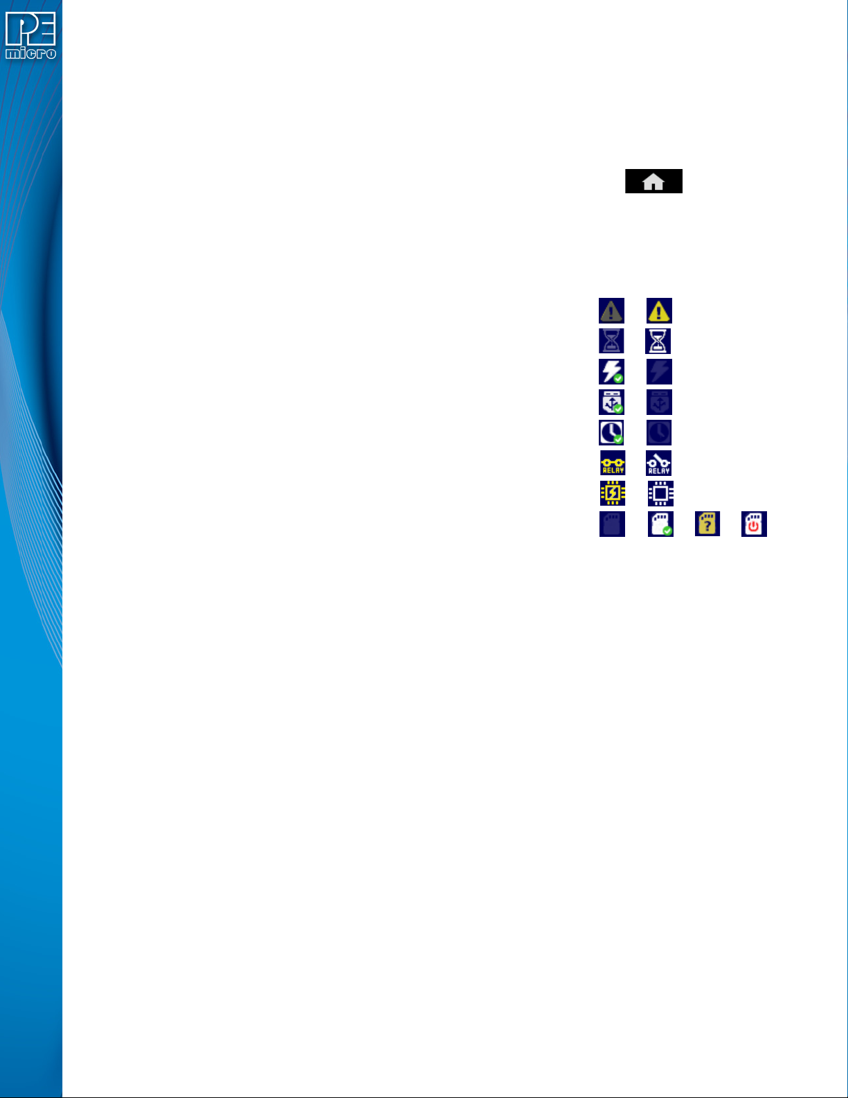
7.3.1 Icons
A row of icons in the upper right corner indicates the status of various attributes of the Cyclone.
Note: The user may tap on the row of icons to view the meaning of each of the currently displayed icons.
Cyclone Unit Status: Ok / Bad
Programming Status: Ready / Busy
Target Power Relays: On / Off
USB-To-PC Enumerated: Yes / No
Real-Time clock Enabled & Working: Yes / No
Cyclone Power Relays: Closed / Open
Target Device Is Powered*: Yes / No
SDHC Memory Card: None / Valid / Unformattted / Reset Cyclone**
* Target Device Is Powered - “Yes” indicates that the Cyclone LC detects power on the Vcc pin of
the target device programming header.
** SDHC Memory Card (Requires SDHC License Activation) - “Reset Cyclone” indicates that the
Cyclone needs to be reset before the SDHC card will register as Valid. The user can push the
Reset button which is located on the front side of the Cyclone, below the LED indicators.
7.3.2 Configurable Display Area
The main area of the home screen can be configured to optionally display the following
information, by using the Cyclone IP Configuration Utility (see Section 5.2.3.5.4 - Configure
Home Screen):
1. Firmware version of the Cyclone (always shown).
2. IP address assigned to the Cyclone.
3. Name assigned to the Cyclone.
4. Number of programming images in the Cyclone’s memory.
5. Name of the selected programming image.
6. First serial number associated with the selected image
7. Current status.
8. Results of the last operation performed.
9. Time and date.
10. Status Window and Main Menu button (always shown).
11. Programming count & limit