CYCLONE-User-Manual.pdf - 第26页
User Manual For Cyclone LC Programmers 26 PIN 7 - TMS/SWDIO GND - PIN 8 PIN 9 - TCK/SWCLK GND - PIN 10 PIN 1 1 - NC* GND - PIN 12 PIN 13 - NC* GND - PIN 14 PIN 15 - RESET GND - PIN 16 PIN 17 - NC* GND - PIN 18 PIN 19 - N…
User Manual For Cyclone LC Programmers 25
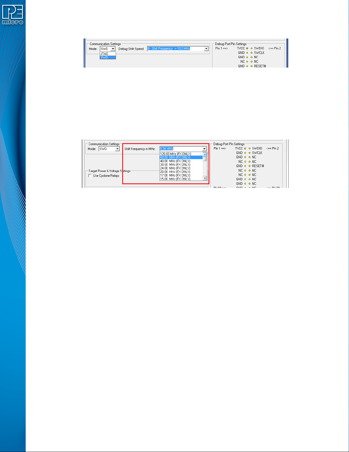
SWD Mode is selected from the “Communication Mode” drop-down box in the Cyclone Image
Creation Utility:
Figure 3-10: Communications Mode Selection
3.17.2.2.1 High-Performance Communications (FX ONLY)
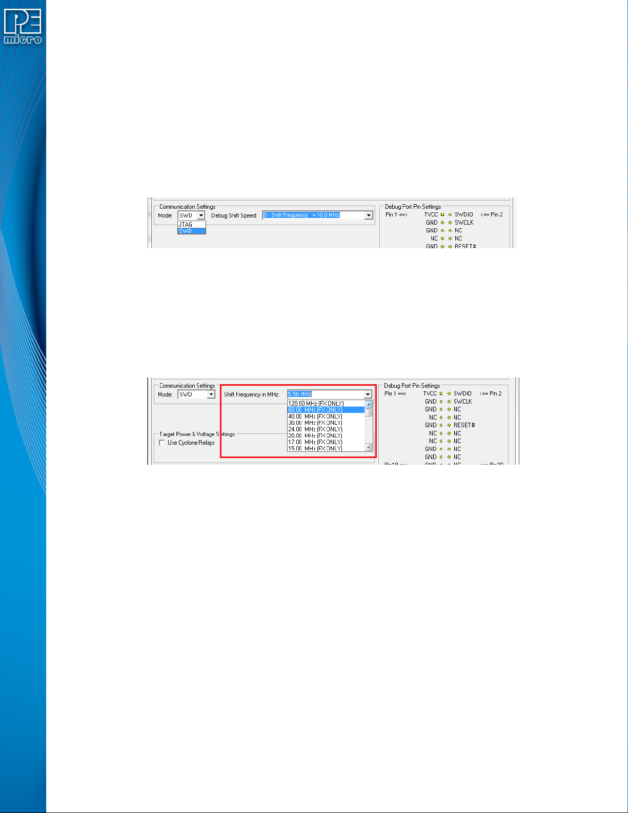
If high-performance options are available for the selected device they will appear in the “Shift
Frequency in M Hz” drop-down. Cyclone FX programmers are capable of high-performance
communications when using certain ARM Cortex targets in SWD mode.
Note: Cyclone LC programmers cannot currently take advantage of high-performance options, although
the frequencies appear in the display.
Figure 3-11: High-Performance Options (FX ONLY)
3.17.3 PORT C: 20-Pin Debug Connector (Kinetis, S32 (ARM), other PEmicro-Supported ARM
devices)
3.17.3.1 JTAG Mode Pin Assignments
The Cyclone provides a 20-pin 0.100-inch pitch double row connector for ARM targets. The
location of the this header is indicated as PORT C under Part# CYCLONE-LC-ARM in Figure 3-5.
The 20-pin standard connector pin definitions for JTAG mode are as follows:
20-Pin Standard Connector JTAG Mode Pin Assignments
PIN 1 - TVCC NC* - PIN 2
PIN 3 - TRST or NC GND - PIN 4
PIN 5 - TDI GND - PIN 6
PIN 7 - TMS GND - PIN 8
PIN 9 - TCK GND - PIN 10
PIN 11 - NC* GND - PIN 12
PIN 13 - TDO GND - PIN 14
PIN 15 - RESET GND - PIN 16
PIN 17 - NC* GND - PIN 18
PIN 19 - NC* GND - PIN 20
Note: *The pin is reserved for internal use within the PEmicro interface.
3.17.3.2 SWD Mode Pin Assignments
Cyclone LC programmers also support SWD Mode. This replaces the JTAG connection with a
clock and single bi-directional data pin.
20-Pin Standard Connector SWD Mode Pin Assignments
PIN 1 - TVCC NC* - PIN 2
PIN 3 - TRST or NC* GND - PIN 4
PIN 5 - NC* GND - PIN 6
User Manual For Cyclone LC Programmers 26
PIN 7 - TMS/SWDIO GND - PIN 8
PIN 9 - TCK/SWCLK GND - PIN 10
PIN 11 - NC* GND - PIN 12
PIN 13 - NC* GND - PIN 14
PIN 15 - RESET GND - PIN 16
PIN 17 - NC* GND - PIN 18
PIN 19 - NC* GND - PIN 20
Note: *The pin is reserved for internal use within the PEmicro interface.
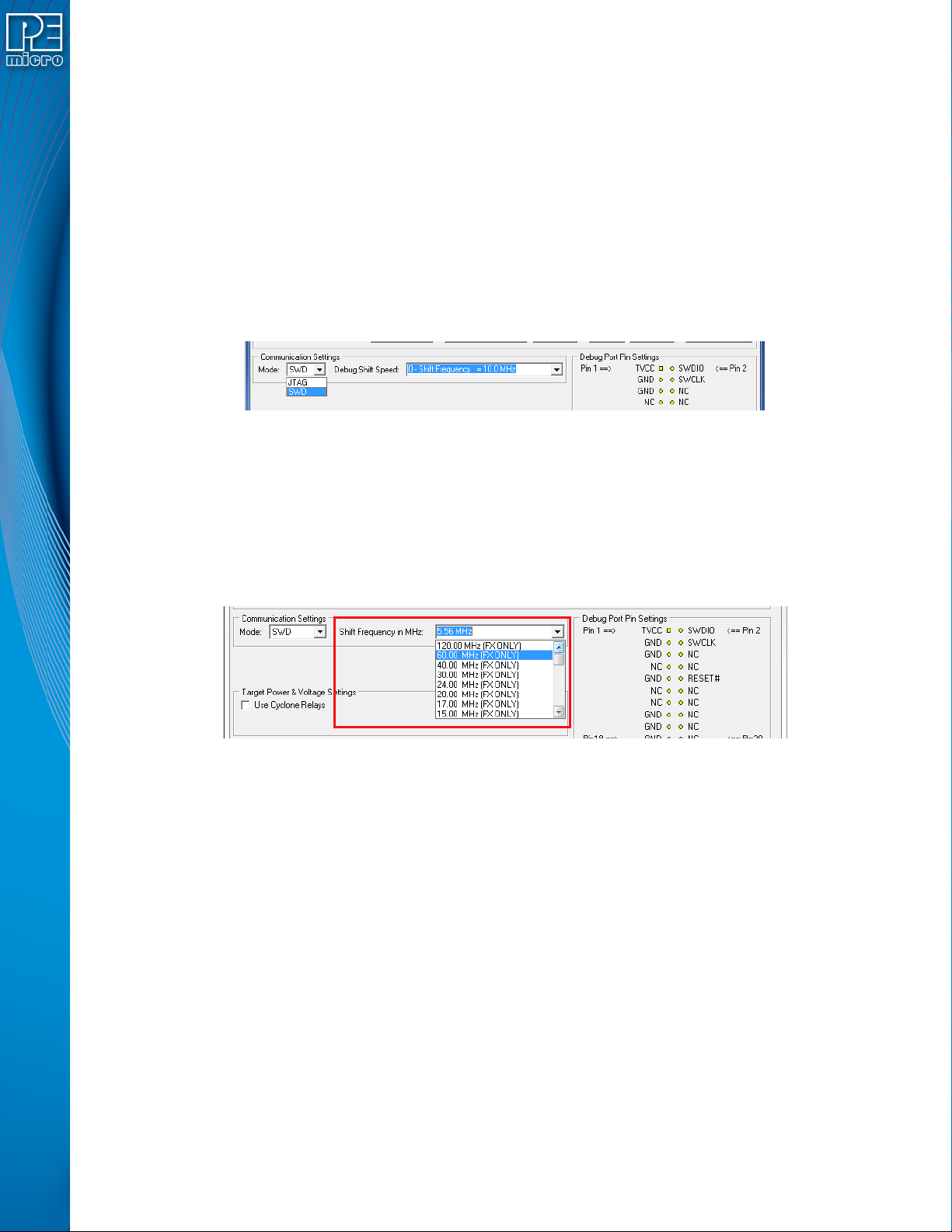
SWD Mode is selected from the “Communication Mode” drop-down box in the Cyclone Image
Creation Utility:
Figure 3-12: Communications Mode Selection
3.17.3.2.1 High-Performance Communications (FX ONLY)
If high-performance options are available for the selected device they will appear in the “Shift
Frequency in MHz” drop-down. Cyclone FX programmers are capable of high-performance
communications when using certain ARM Cortex targets in SWD mode.
Note: Cyclone LC programmers cannot currently take advantage of high-performance options, although
the frequencies appear in the display.
Figure 3-13: High-Performance Options (FX ONLY)
3.18 Target Headers For Part# CYCLONE-LC-UNIV
PEmicro Part# CYCLONE-LC-UNIV features 6 ports labeled A-H.
3.18.1 PORT A: 10-Pin Keyed Mini Connector (Kinetis, S32 (ARM), other PEmicro-Supported ARM
devices)
3.18.1.1 JTAG Mode Pin Assignments
The Cyclone provides a keyed 10-pin 0.050-inch pitch double row connector for ARM targets. The
location of the this header is indicated as PORT A in Figure 3-5. The 10-pin keyed mini connector
pin definitions for JTAG mode are as follows:
10-Pin Keyed Mini Connector JTAG Mode Pin Assignments
PIN 1 - TVCC TMS - PIN 2
PIN 3 - GND TCK - PIN 4
PIN 5 - GND TDO - PIN 6
PIN 7 - NC TDI - PIN 8
PIN 9 - NC* RESET - PIN 10
*The pin is reserved for internal use within the PEmicro interface.
User Manual For Cyclone LC Programmers 27
3.18.1.2 SWD Mode Pin Assignments
Cyclone LC programmers also support SWD Mode. This replaces the JTAG connection with a
clock and single bi-directional data pin.
10-Pin Keyed Mini Connector SWD Mode Pin Assignments
PIN 1 - TVCC TMS/SWDIO - PIN 2
PIN 3 - GND TCK/SWCLK - PIN 4
PIN 5 - GND NC* - PIN 6
PIN 7 - NC NC* - PIN 8
PIN 9* - NC RESET - PIN 10
*The pin is reserved for internal use within the PEmicro interface.
SWD Mode is selected from the “Communication Mode” drop-down box in the Cyclone Image
Creation Utility:
Figure 3-14: Communications Mode Selection
3.18.1.2.1 High-Performance Communications (FX ONLY)
If high-performance options are available for the selected device they will appear in the “Shift
Frequency in MHz” drop-down. Cyclone FX programmers are capable of high-performance
communications when using certain ARM Cortex targets in SWD mode.
Note: Cyclone LC programmers cannot currently take advantage of high-performance options, although
the frequencies appear in the display.
Figure 3-15: High-Performance Options (FX ONLY)
3.18.2 PORT B: 20-Pin Keyed Mini Connector (Kinetis, S32 (ARM), other PEmicro-Supported ARM
devices)
3.18.2.1 JTAG Mode Pin Assignments
The Cyclone provides a keyed 20-pin 0.050-inch pitch double row connector for ARM targets. The
location of the this header is indicated as PORT B in Figure 3-5. The 20-pin keyed mini connector
pin definitions for JTAG mode are as follows:
20-Pin Keyed Mini Connector JTAG Mode Pin Assignments
PIN 1 - TVCC TMS - PIN 2
PIN 3 - GND TCK - PIN 4
PIN 5 - GND TDO - PIN 6
PIN 7 - NC TDI - PIN 8
PIN 9 - NC* RESET - PIN 10
PIN 11 - NC NC* - PIN 12
PIN 13 - NC NC* - PIN 14
PIN 15 - GND NC* - PIN 16
PIN 17 - GND NC* - PIN 18
PIN 19 - GND NC* - PIN 20