CYCLONE-User-Manual.pdf - 第31页
User Manual For Cyclone LC Programmers 31 *The pin is reserved for internal use within the PEmicro interface. **The pin is reserved for internal use within the PEmicro interface only when using an MR8 target. 3.18.6 PORT…
User Manual For Cyclone LC Programmers 30
DDATA0 19 20 GND
N/C 21 22 N/C
GND 23 24 CLK
VCC 25 26 TEA
*The pin is reserved for internal use within the PEmicro interface.
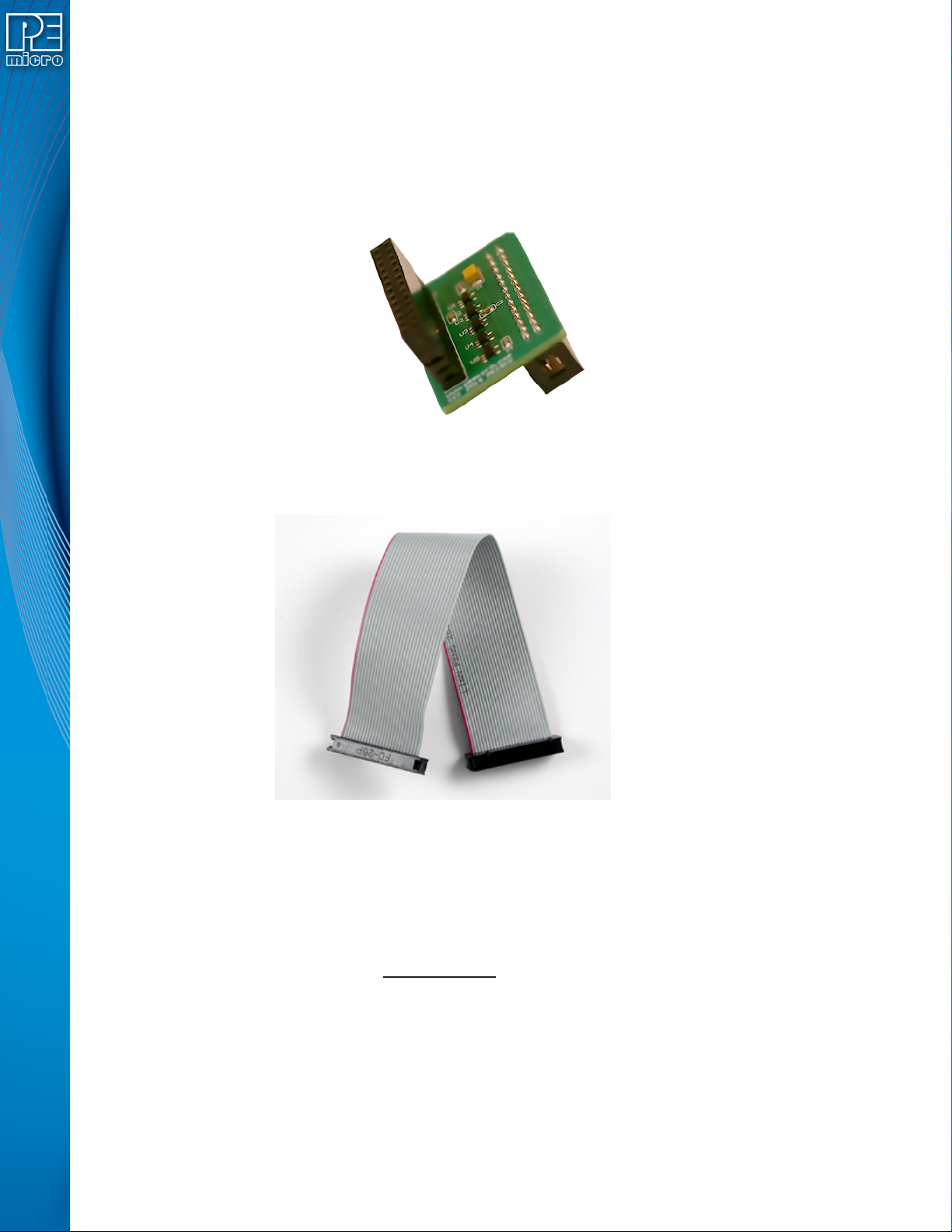
The ColdFire adapter for Synchronous targets and ribbon cable for Asynchronous targets is
pictured below:
Figure 3-19: ColdFire Adapter (part# CABLE_CF_ADAPTER (Rev. B), for synchronous ColdFire
targets, sold separately)
Figure 3-20: ColdFire Ribbon Cable (for asynchronous ColdFire targets, included with Cyclone)
3.18.5 PORT E: 16-Pin Debug Connector (MON08)
The Cyclone provides a 16-pin 0.100-inch pitch double row connector for MON08 targets. The
location of the this header is indicated as PORT E in Figure 3-5. The MON08 header adopts the
standard pin-out from MON08 debugging with some modifications. The general pin-out is as
follows:
MON08 Signals
PIN 1 - NC* GND - PIN 2
PIN 3 - NC** RST - PIN 4
PIN 5 - NC* IRQ - PIN 6
PIN 7 - NC* MON4 - PIN 8
PIN 9 - NC* MON5 - PIN10
PIN11 - NC* MON6 - PIN12
PIN13 - OSC MON7 - PIN14
PIN15 - Vout MON8 - PIN16
User Manual For Cyclone LC Programmers 31
*The pin is reserved for internal use within the PEmicro interface.
**The pin is reserved for internal use within the PEmicro interface only when using an MR8 target.
3.18.6 PORT F: 6-Pin Debug Connector (RS08, HCS08, HC(S)12(X), S12Z, ColdFire +/V1, STM8 w/
adapter)
The Cyclone provides a standard 6-pin 0.100-inch pitch dual row 0.025-inch square header for
ColdFire V1, S12Z, 68(S)12(X), 68HCS08, RS08, and STMicroelectronics’ STM8 targets. The
location of the this header is indicated as PORT F in Figure 3-5. The header uses the NXP
standard pin configuration, listed here for reference:
ColdFire V1, 68(S)12(X), 68HCS08, and RS08 Signals
PIN 1 - BKGD GND - PIN 2
PIN 3 - NC RESET - PIN 4
PIN 5 - NC TVCC - PIN 6
S12Z Signals
Note:* indicates optional signal
PIN 1 - BKGD GND - PIN 2
PIN 3 - PDO* RESET - PIN 4
PIN 5 - PDOCLK* TVCC - PIN 6
6-Pin STM8 Signals
PIN 1 -SWIM** GND - PIN 2
PIN 3 - NC* RESET - PIN 4
PIN 5 - NC* TVCC - PIN 6
*The pin is reserved for internal use within the PEmicro interface.
** All the signals are direct connect except the SWIM line which requires a 680 Ohm pull-up
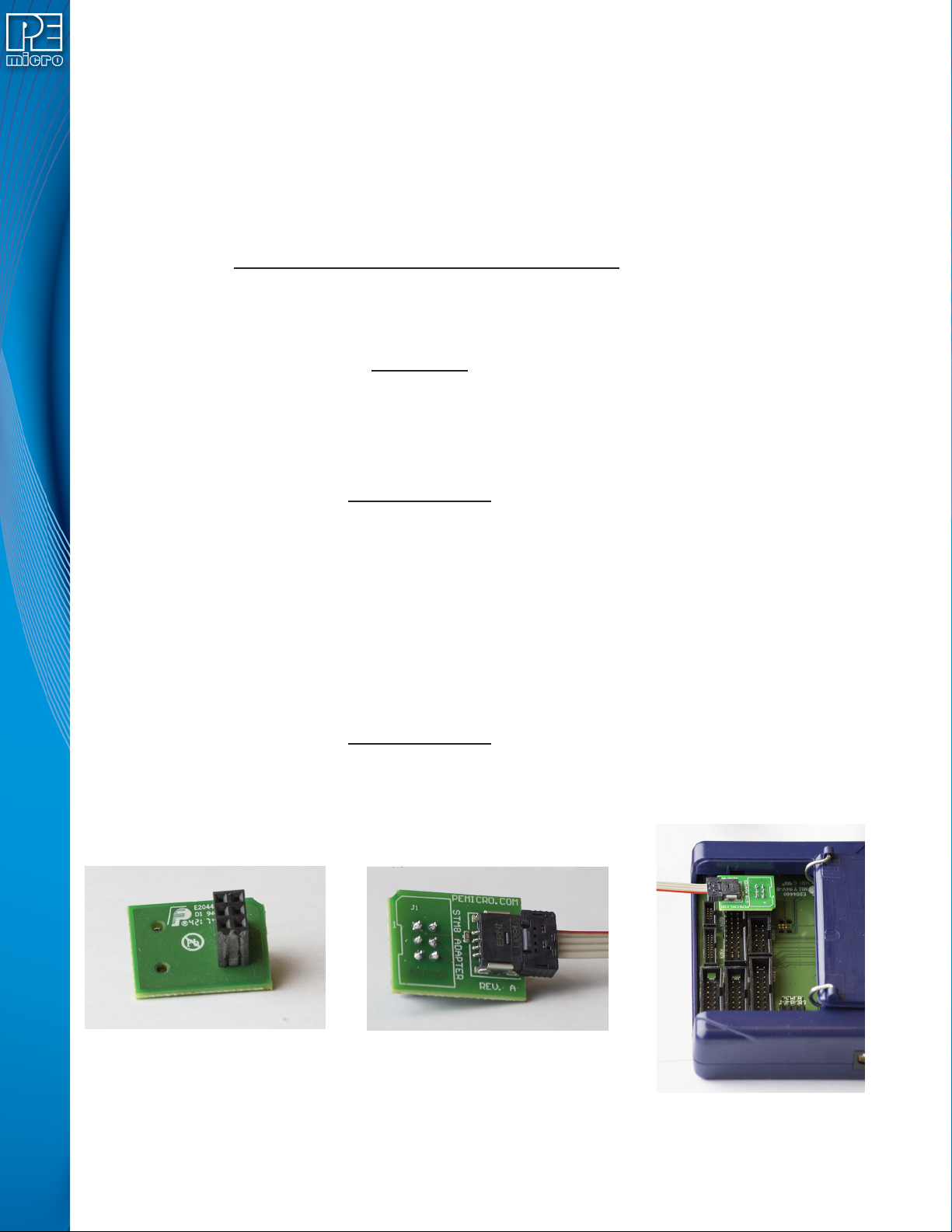
PEmicro also offers a separate STM8 adapter (part# CU-CUFX-STM8-ADPT) that can be plugged
into the 6-pin header of the Cyclone (see Figure 3-21). The adapter offers 4 pins signals from an
ERNI connector.
4-Pin STM8 Signals
(Requires STM8 Adapter, sold separately)
PIN 1 - TVCC SWIM - PIN 2
PIN 3 - GND RESET - PIN 4
Figure 3-21: STM8 Adapter: 1) Bottom, 2) Top, 3) Connected To 6-Pin Header of Cyclone_Universal
(Adapter Sold Separately)

User Manual For Cyclone LC Programmers 32
3.18.7 PORT G: 10-Pin Debug Connector (Power MPC5xx/8xx)
The Cyclone provides a standard 10-pin 0.100-inch pitch dual row 0.025-inch square header for
Power MPC5xx/8xx BDM targets. The location of the this header is indicated as PORT G in Figure
3-5.
Power MPC5xx/8xx BDM Pinout
NC* 12SRESET#
GND 34DSCLK
GND 56NC*
HRESET# 78DSDI
VDD 910DSDO
*The pin is reserved for internal use within the PEmicro interface.
3.18.8 PORT H: 20-Pin Debug Connector (Kinetis, S32 (ARM), other PEmicro-Supported ARM
devices)
3.18.8.1 JTAG Mode Pin Assignments
The Cyclone provides a 20-pin 0.100-inch pitch double row connector for ARM targets. The
location of the this header is indicated as PORT H under Part# CYCLONE-LC-UNIV in Figure 3-5.
The 20-pin standard connector pin definitions for JTAG mode are as follows:
20-Pin Standard Connector JTAG Mode Pin Assignments
PIN 1 - TVCC NC - PIN 2*
PIN 3 - TRST or NC* GND - PIN 4
PIN 5 - TDI GND - PIN 6
PIN 7 - TMS GND - PIN 8
PIN 9 - TCK GND - PIN 10
PIN 11 - NC* GND - PIN 12
PIN 13 - TDO GND - PIN 14
PIN 15 - RESET GND - PIN 16
PIN 17 - NC* GND - PIN 18
PIN 19 - NC* GND - PIN 20
*The pin is reserved for internal use within the PEmicro interface.
3.18.8.2 SWD Mode Pin Assignments
Cyclone LC programmers also support SWD Mode. This replaces the JTAG connection with a
clock and single bi-directional data pin.
20-Pin Standard Connector SWD Mode Pin Assignments
PIN 1 - TVCC NC* - PIN 2
PIN 3 - TRST or NC* GND - PIN 4
PIN 5 - NC* GND - PIN 6
PIN 7 - TMS/SWDIO GND - PIN 8
PIN 9 - TCK/SWCLK GND - PIN 10
PIN 11 - NC* GND - PIN 12
PIN 13 - NC* GND - PIN 14
PIN 15 - RESET GND - PIN 16
PIN 17 - NC* GND - PIN 18
PIN 19 - NC* GND - PIN 20
*The pin is reserved for internal use within the PEmicro interface.
SWD Mode is selected from the “Communication Mode” drop-down box in the Cyclone Image
Creation Utility: