CYCLONE-User-Manual.pdf - 第90页
User Manual For Cyclone LC Programmers 90 8.3.3.3 Programming Dynamic Data Here, a Cyclone is connected via the Serial port and is identified by name rather than IP address. After executing image #1 on both cyclones, we …

User Manual For Cyclone LC Programmers 89
-firmwareupdate=[firmware update mode]
Set the firmware update mode to “auto”, “dontupdate”, “forceupdate”. The default mode is “auto.”
-help
Display a list of available commands.
The following command-line parameters require a Cyclone FX, or a Cyclone LC with the
ProCryption Security Activation License.
-listencryptionkeys
List Encryption Key Files that reside on Cyclone
-addencryptionkey=[file path]
Add ImageKey file to Cyclone. The file path is the path to the ImageKey.
-deleteencryptionkey=[object ID or display index]
Delete ImageKey File from Cyclone. Can be deleted by ID, or by display index number (-
listencryptionkeys returns a numbered list of ImageKeys; the display index corresponds to these
numbers).
8.3.3 Examples
The commands should be separated by a space. Every command starts with a “-” character,
arguments follow the “=” character.
8.3.3.1 Typical Usage
This example connects to a single Cyclone identified by its IP address 10.0.1.1 and executes its
first image. This is the most common usage of the Cyclone Control Utility.
This example connects to a single Cyclone enumerated on USB1 and executes its first image.
8.3.3.2 Controlling Multiple Cyclones
This example connects to three separate Cyclone units. Two units are connected via USB
(10.0.1.1 and 10.0.1.2) and the third is connected via Ethernet (10.0.1.3). The three Cyclone units
are configured to execute image #2.
CycloneControlConsole.exe –cyclone=10.0.1.1 –launchimage=1
CycloneControlConsole.exe –cyclone=USB1 –launchimage=1
CycloneControlConsole.exe –cyclone=USB1,10.0.1.2,10.0.1.3 –
launchimage=2

User Manual For Cyclone LC Programmers 90
8.3.3.3 Programming Dynamic Data
Here, a Cyclone is connected via the Serial port and is identified by name rather than IP address.
After executing image #1 on both cyclones, we write 6 bytes of dynamic data on Cyclone #2
starting at address 0x1080. Note that all parameters for the “-putdynamicdata” command should
be hexadecimal values.
8.3.3.4 Executing more than 1 image on the same Cyclone
Two Cyclone units are connected via Ethernet and both Cyclone units execute their first image.
Afterwards, the both Cyclones will execute their second image.
This example is useful when the processor’s code is split into two separate images. For example,
one image could contain the bootloader while the second image contains the main application
code.
8.3.3.5 Image Management – Modifying External Images
In this example, a Cyclone unit is connected via USB and it has an image stored on its external
memory card. The external image is erased and a new one is added. This type of command
should only be used when an image needs to be updated.
8.3.3.6 Image Management – Modifying Images on Two Cyclones in Parallel
In this example, two Cyclone units connected via USB have their images erased and a new image
is added to both Cyclone units. This type of command should only be executed when images need
to be updated.
8.4 Cyclone Control GUI
As part of the Cyclone Control Suite, PEmicro includes the Cyclone Control GUI, a graphical
application that gives the users access to all the functions of the latest Cyclone Control.
Note: This new application replaces the previous Image Manager Utility and Cyclone Config IP Utility.
The Cyclone Control GUI allows users to add and remove images from the internal Cyclone
memory as well as from the external memory cards. The utility also allows the user to view and edit
Cyclone properties, to view the Cyclone LCD remotely, to view and add Cyclone Licenses, and to
CycloneControlConsole.exe –cyclone=CycloneFX_Table1,CycloneFX_Table2
–launchimage=1 –putdynamicdata=2,1080,45,44,49,53,4F,4E
CycloneControlConsole.exe –cyclone=CycloneFX_1,CycloneFX_2
–launchimage=1 –launchimage=2
CycloneControlConsole.exe –cyclone=USB1 –eraseallexternalimages
–addexternalimage=c:\images\externalImage1.SAP
CycloneControlConsole.exe –cyclone=USB1,USB2 –eraseallinternalimages
–addinternalimage=c:\images\Image1.SAP
User Manual For Cyclone LC Programmers 91
view and manage Serial Files and Encryption Keys.
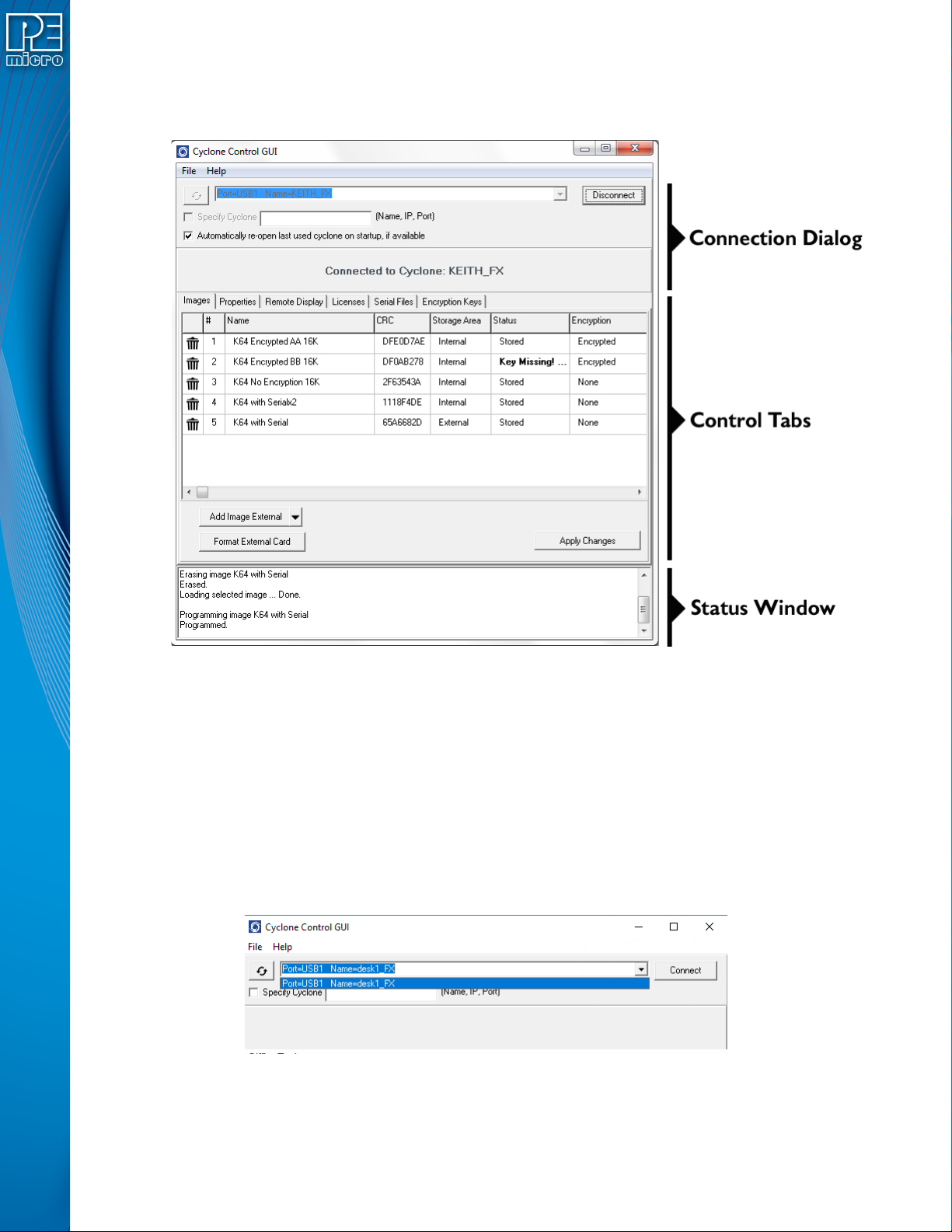
The utility is composed of three main parts: a connection dialog, the control tabs, and a status
window.
Figure 8-2: Areas of the Cyclone Control GUI
8.4.1 The Connection Dialog
Allows the user to specify a Cyclone to connect with, as well as specify the connection options.
The utility will always automatically upgrade the firmware of a Cyclone if the firmware in the
Cyclone is outdated. However, firmware update can also be forced by using the checkbox in File-
>Force Firmware Update. This option will update the firmware on the Cyclone with the latest
firmware in the same folder as the Cyclone Control GUI.
At launch, the Cyclone Control GUI will show all the Cyclones detected on the network and those
attached by USB connections in a drop-down list. Cyclones can also be connected to by using the
“Specify Cyclone” checkbox and specifying a Cyclone by identifier. This identifier can by the
Cyclone name, its IP address or its port number.
Figure 8-3: Select Cyclone From Drop Down
Once the Cyclone is selected, clicking on the “Connect” button will bring a series of tabs that will
allow full access to the Cyclone.