CYCLONE-User-Manual.pdf - 第37页
User Manual For Cyclone LC Programmers 37 Figure 4-6: Power Provided by the Cyclone to the Debug Cable 4.2.3 External Power passed through the Cyclone and out 2.5 mm barrel port It is also possible to provide external po…
User Manual For Cyclone LC Programmers 36
After the basic hardware setup, target power and voltage settings are also set in the creation of a
SAP (stand-alone programming) image. At a minimum the SAP image contains all the commands
to Erase, Program, and Verify a programming image. More sophisticated power selections in the
SAP image can control the relays, target voltage, delays, and power down after SAP operations,
as shown in the selection dialog.
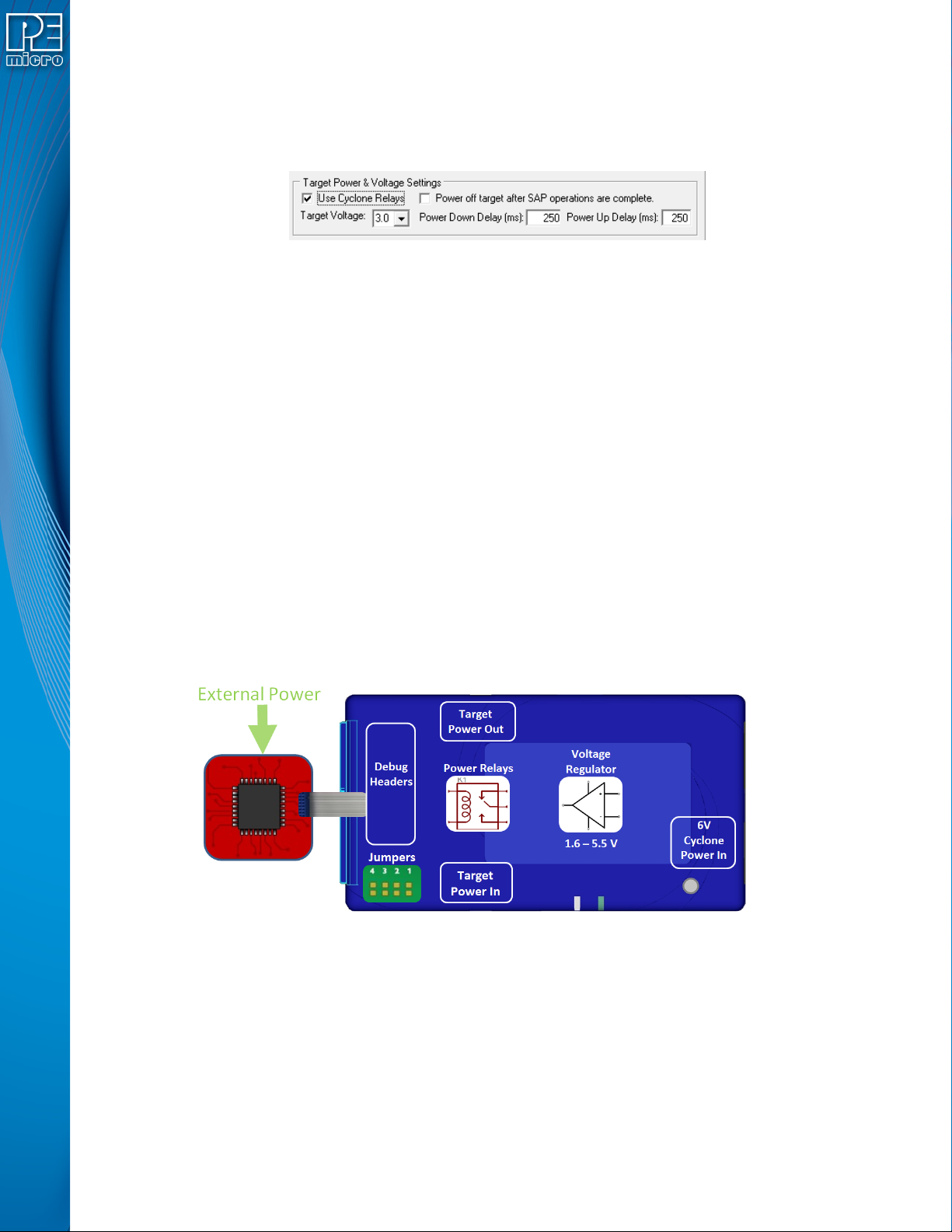
Figure 4-4: Target Power & Voltage Settings
Target voltages (with appropriate jumper settings) in the range of 1.6 to 5.5 volts may be provided.
There is also the option to select the internal Cyclone relays to power cycle the Cyclone during
programming, and set the length of delays during power up and down. This is extremely useful to
make sure the power is off when hooking up the target. Power cycling is especially important for
architectures that require it to enter debug mode. The SAP image settings may even be used to
turn off the target power once programming is completed, to ensure that the microcontroller is left
in a halted state and not running.
4.2 Cyclone Setup
Below is a tutorial that demonstrates how to set up the Cyclone LC in each of the 5 power
configurations. A very common configuration is the independently powered target. In this power
scenario, the Cyclone will detect and use the power on the target for the appropriate debug
communication voltages.
4.2.1 Independently Powered Target
In the simplest and most common scenario, no jumpers are set, so the target is powered
independently from the Cyclone. No power is passed through the debug header, just the standard
debug signals. The Cyclone automatically detects the target power and sets the debug signals to
match.
Figure 4-5: Independently Powered Target
4.2.2 Power provided by the Cyclone to the debug cable
It is also possible for the Cyclone to generate power through an internal regulator in the range of
1.6 to 5.5 Volts. In the jumper configuration below, the Cyclone generates the power through a
voltage regulator, and passes it through the power relays and out through the debug ribbon cable,
which is set up during the SAP image creation. There is only one connection to the target
processor which will handle both the communication and the power. In this scenario, external
power must not be connected to the Power In jack since it is already being provided.
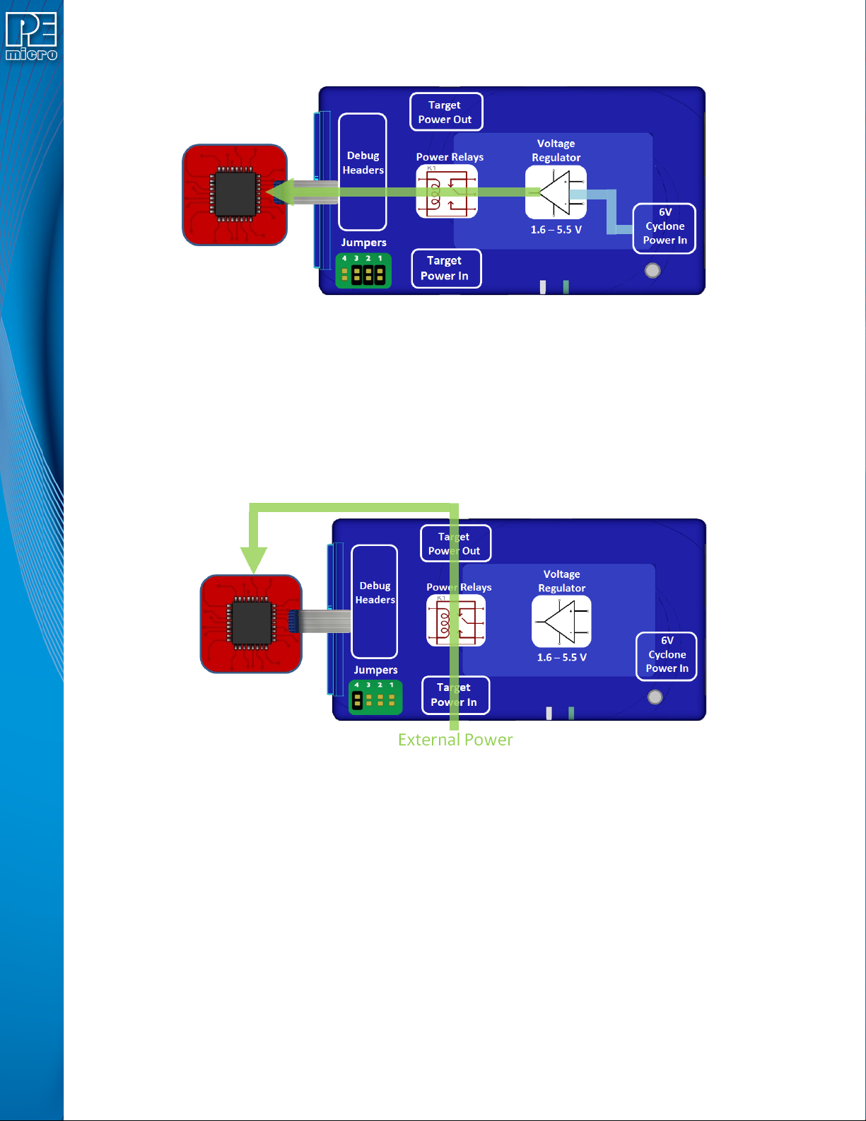
User Manual For Cyclone LC Programmers 37
Figure 4-6: Power Provided by the Cyclone to the Debug Cable
4.2.3 External Power passed through the Cyclone and out 2.5 mm barrel port
It is also possible to provide external power, passed through the Cyclone power relays, and back
out to be available to power the target board externally. This is useful when the user wants to
control the power to the target and the target board has an external power connector. Setting a
single jumper will connect the barrel port input connector on the bottom edge of the Cyclone,
through the relays, to a matched 2.5 mm barrel port output connector on the top edge of the
Cyclone, so that the power can be routed into and back out of the Cyclone.
Figure 4-7: External Power Passed Through the Cyclone and Out 2.5 mm Barrel Port
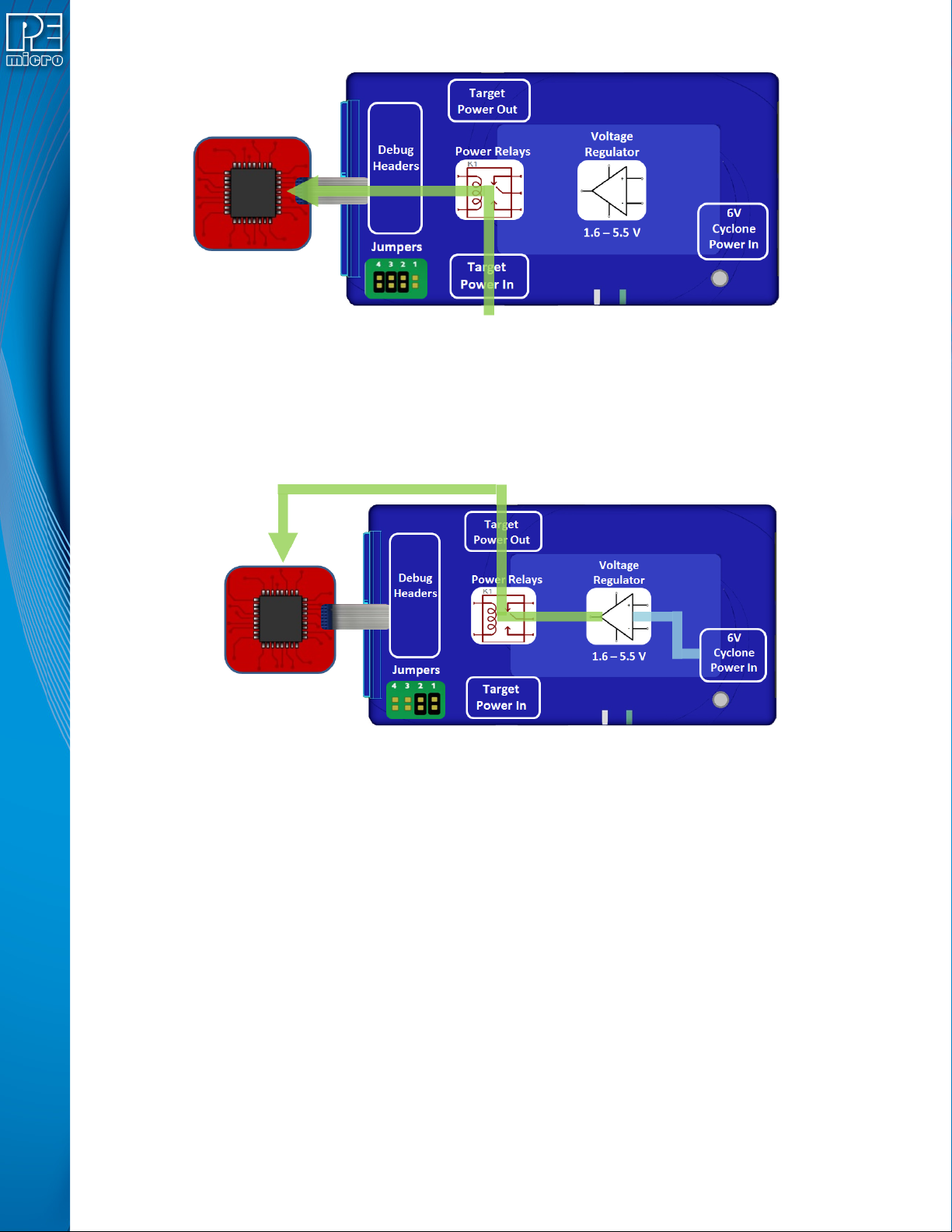
4.2.4 External Power passed through the Cyclone to the debug cable
In a slightly different scenario, the user may wish to provide power to the target through the debug
cable. On the bottom edge of the Cyclone is a 2.5 mm Power In port barrel which will pass power
through target relays which lets the Cyclone take control of the power cycling during programming.
This simple setup requires only an input to the Cyclone and a single ribbon cable connection to the
target board that handles both communication and power. The external power provided must be
between 1.6 to 5.5 volts.
User Manual For Cyclone LC Programmers 38
Figure 4-8: External Power Passed Through the Cyclone to the Debug Cable
4.2.5 Power provided by the Cyclone and out 2.5 mm barrel port
In a slightly different scenario, the user may wish to have the Cyclone provide power, but power
the target via an external connector on the target. The voltage supplied to the target is determined
by the settings in the SAP image. When generating the SAP image the Cyclone relays must be
selected as well as the correct voltage level for the target.
Figure 4-9: Power Provided by the Cyclone and Out 2.5 mm Barrel Port
4.3 Setup Reminders
The most important step when providing power out to a target is to check the Cyclone's jumper
settings to make sure they match the intended power setup. The jumpers control the power
settings which determine how power is supplied, regardless of the SAP image settings. If the
jumpers are set for power to be provided through the Cyclone, and the target is externally
powered, this is a conflict and may cause damage to the board.
In the case where power is being supplied through the Cyclone and the target is not being
powered on, the user should first check the jumper settings to make sure they match the
intended power setup. Second, the user should check to make sure the SAP image has the ‘Use
Cyclone Relays’ box checked with the appropriate voltage level selected.