CYCLONE-User-Manual.pdf - 第39页
User Manual For Cyclone LC Programmers 39 5 TOUCHSCREEN LCD MENU This chapter describes the Cyclone’s touchscreen LCD menu. Figure 5-1 shows an overview of the menu structure. Note: This menu will change as features are …
User Manual For Cyclone LC Programmers 38
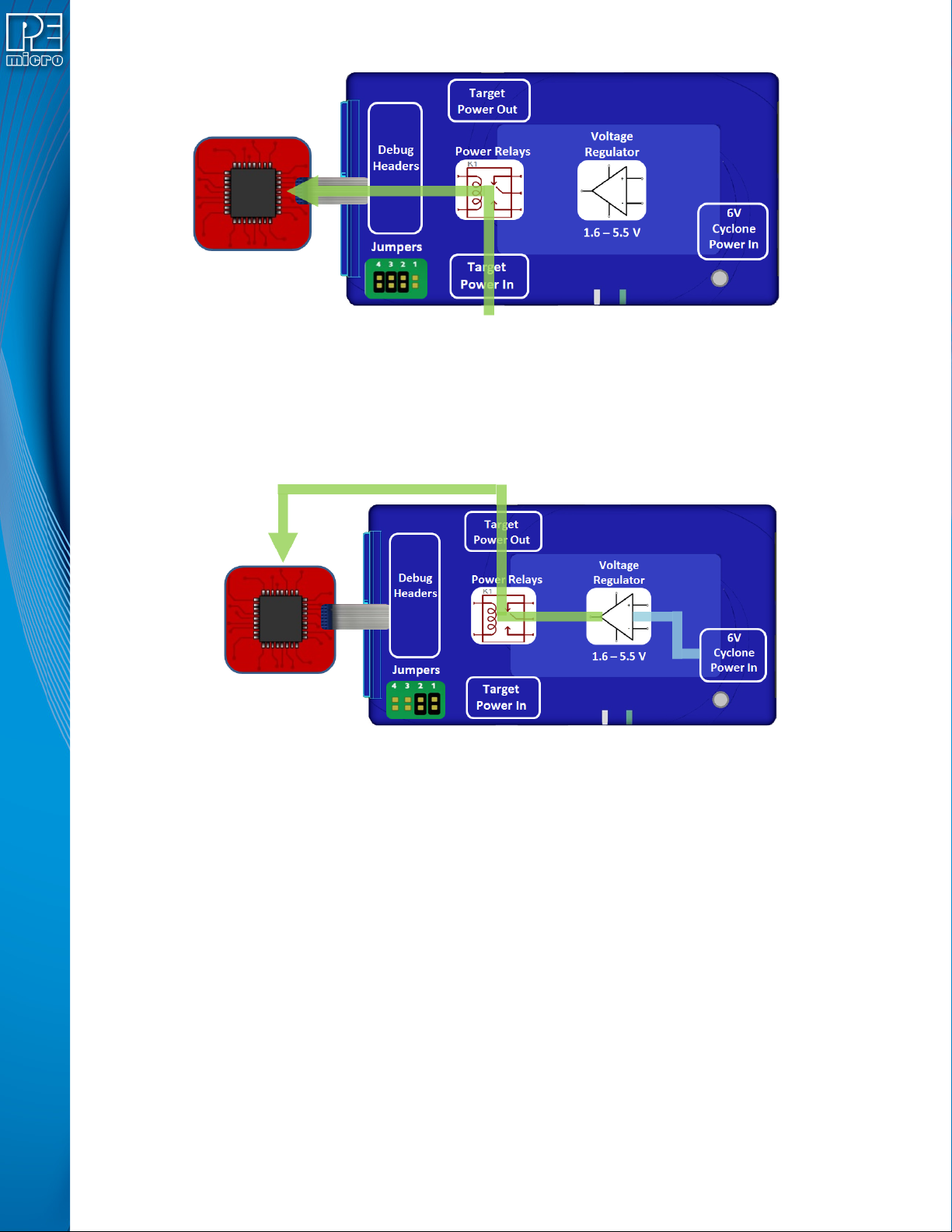
Figure 4-8: External Power Passed Through the Cyclone to the Debug Cable
4.2.5 Power provided by the Cyclone and out 2.5 mm barrel port
In a slightly different scenario, the user may wish to have the Cyclone provide power, but power
the target via an external connector on the target. The voltage supplied to the target is determined
by the settings in the SAP image. When generating the SAP image the Cyclone relays must be
selected as well as the correct voltage level for the target.
Figure 4-9: Power Provided by the Cyclone and Out 2.5 mm Barrel Port
4.3 Setup Reminders
The most important step when providing power out to a target is to check the Cyclone's jumper
settings to make sure they match the intended power setup. The jumpers control the power
settings which determine how power is supplied, regardless of the SAP image settings. If the
jumpers are set for power to be provided through the Cyclone, and the target is externally
powered, this is a conflict and may cause damage to the board.
In the case where power is being supplied through the Cyclone and the target is not being
powered on, the user should first check the jumper settings to make sure they match the
intended power setup. Second, the user should check to make sure the SAP image has the ‘Use
Cyclone Relays’ box checked with the appropriate voltage level selected.
User Manual For Cyclone LC Programmers 39
5 TOUCHSCREEN LCD MENU
This chapter describes the Cyclone’s touchscreen LCD menu. Figure 5-1 shows an overview of
the menu structure.
Note: This menu will change as features are added to the Cyclone LC, so if your menu does not match
what is displayed here, please check PEmicro’s website, www.pemicro.com, for a user manual
containing the latest LCD Menu operations information.
5.1 Home Screen
The home screen appears when the Cyclone LC is powered on, or when the Home
button is tapped.
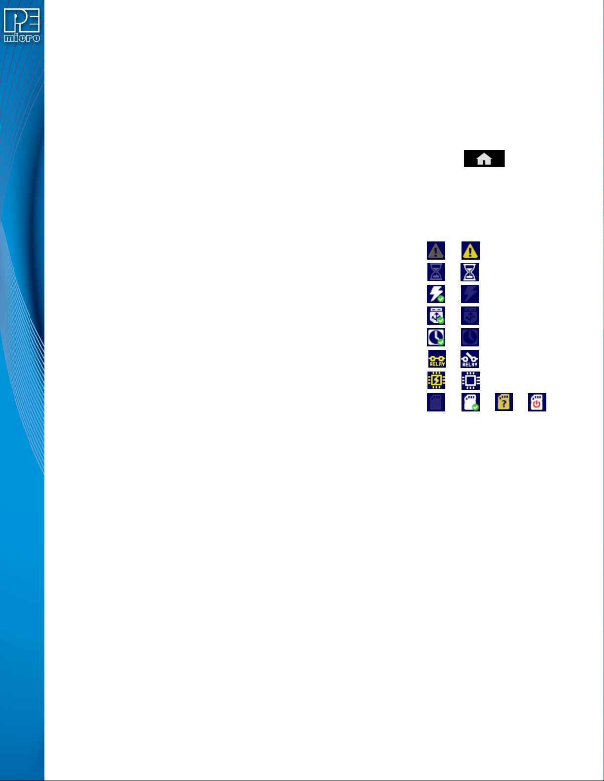
5.1.1 Icons
A row of icons in the upper right corner indicates the status of various attributes of the Cyclone.
Note: The user may tap on the row of icons to view the meaning of each of the currently displayed icons.
Cyclone Unit Status: Ok / Bad
Programming Status: Ready / Busy
Target Power Relays: On / Off
USB-To-PC Enumerated: Yes / No
Real-Time clock Enabled & Working: Yes / No
Cyclone Power Relays: Closed / Open
Target Device Is Powered*: Yes / No
SDHC Memory Card: None / Valid / Unformattted / Reset Cyclone**
* Target Device Is Powered - “Yes” indicates that the Cyclone LC detects power on the Vcc pin of
the target device programming header.
** SDHC Memory Card (Requires SDHC Activation License) - “Reset Cyclone” indicates that the
Cyclone needs to be reset before the SDHC card will register as Valid. The user can push the
Reset button which is located on the front side of the Cyclone, below the LED indicators.
5.1.2 Configurable Display Area
The main area of the home screen can be configured to optionally display the following
information, by using the Cyclone IP Configuration Utility (see Section 5.2.3.5.4 - Configure
Home Screen):
1. Firmware version of the Cyclone (always shown).
2. IP address assigned to the Cyclone.
3. Name assigned to the Cyclone.
4. Number of programming images in the Cyclone’s memory.
5. Name of the selected programming image.
6. First serial number associated with the selected image
7. Current status.
8. Results of the last operation performed.
9. Time and date.
User Manual For Cyclone LC Programmers 40
10. Status Window and Main Menu button (always shown).
11. Programming count & limit
12.
5.1.3 Status Window
The status window appears in the lower left corner of the home screen and displays the results of
programming operations.
5.1.4 Error Information Icon
When the Cyclone experiences an error during programming operations, the Info icon will appear
to the left of the Menu button (or AUX button, if configured).
Info Icon:
Press the Info icon to view a detailed description of the error.
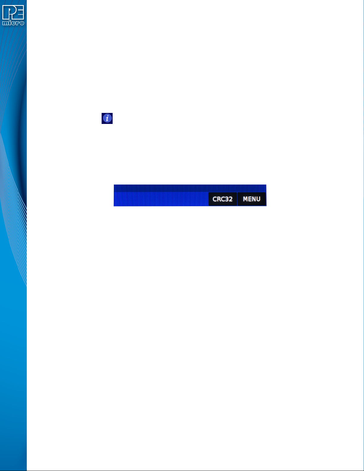
5.1.5 AUX Button (Appears If Configured)
The Cyclone allows the user to add an Auxiliary (AUX) button to the home screen which will
perform a specific function when pressed. The specific function is chosen by the user when the
AUX button is configured. The AUX button will appear on the home screen to the left of the “Menu”
button, in the lower right corner of the home screen.
Figure 5-1: AUX Button On Home Screen (configured to perform CRC32 function)
For information on how to configure the AUX button, see Section 5.2.4 - Status.
5.2 Main Menu
The Main Menu is accessible by pressing the “Menu” button when the Home Screen is displayed.
The Main Menu contains the following selections: