CYCLONE-User-Manual.pdf - 第33页
User Manual For Cyclone LC Programmers 33 Figure 3-22: Communications Mode Selection 3.18.8.2.1 High-Performance Communications (FX ONL Y) If high-performance options are available for the selected device they will appea…

User Manual For Cyclone LC Programmers 32
3.18.7 PORT G: 10-Pin Debug Connector (Power MPC5xx/8xx)
The Cyclone provides a standard 10-pin 0.100-inch pitch dual row 0.025-inch square header for
Power MPC5xx/8xx BDM targets. The location of the this header is indicated as PORT G in Figure
3-5.
Power MPC5xx/8xx BDM Pinout
NC* 12SRESET#
GND 34DSCLK
GND 56NC*
HRESET# 78DSDI
VDD 910DSDO
*The pin is reserved for internal use within the PEmicro interface.
3.18.8 PORT H: 20-Pin Debug Connector (Kinetis, S32 (ARM), other PEmicro-Supported ARM
devices)
3.18.8.1 JTAG Mode Pin Assignments
The Cyclone provides a 20-pin 0.100-inch pitch double row connector for ARM targets. The
location of the this header is indicated as PORT H under Part# CYCLONE-LC-UNIV in Figure 3-5.
The 20-pin standard connector pin definitions for JTAG mode are as follows:
20-Pin Standard Connector JTAG Mode Pin Assignments
PIN 1 - TVCC NC - PIN 2*
PIN 3 - TRST or NC* GND - PIN 4
PIN 5 - TDI GND - PIN 6
PIN 7 - TMS GND - PIN 8
PIN 9 - TCK GND - PIN 10
PIN 11 - NC* GND - PIN 12
PIN 13 - TDO GND - PIN 14
PIN 15 - RESET GND - PIN 16
PIN 17 - NC* GND - PIN 18
PIN 19 - NC* GND - PIN 20
*The pin is reserved for internal use within the PEmicro interface.
3.18.8.2 SWD Mode Pin Assignments
Cyclone LC programmers also support SWD Mode. This replaces the JTAG connection with a
clock and single bi-directional data pin.
20-Pin Standard Connector SWD Mode Pin Assignments
PIN 1 - TVCC NC* - PIN 2
PIN 3 - TRST or NC* GND - PIN 4
PIN 5 - NC* GND - PIN 6
PIN 7 - TMS/SWDIO GND - PIN 8
PIN 9 - TCK/SWCLK GND - PIN 10
PIN 11 - NC* GND - PIN 12
PIN 13 - NC* GND - PIN 14
PIN 15 - RESET GND - PIN 16
PIN 17 - NC* GND - PIN 18
PIN 19 - NC* GND - PIN 20
*The pin is reserved for internal use within the PEmicro interface.
SWD Mode is selected from the “Communication Mode” drop-down box in the Cyclone Image
Creation Utility:
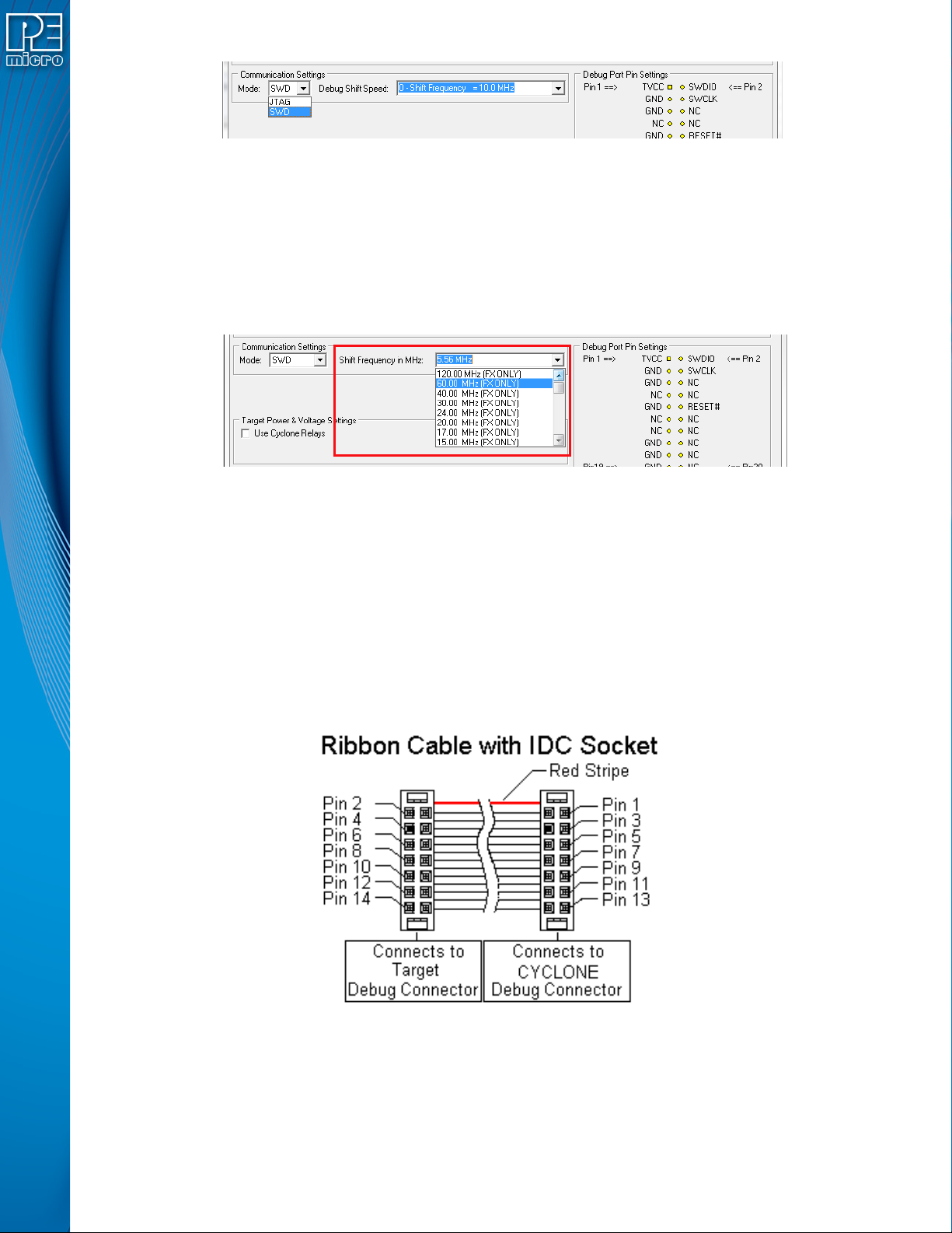
User Manual For Cyclone LC Programmers 33
Figure 3-22: Communications Mode Selection
3.18.8.2.1 High-Performance Communications (FX ONLY)
If high-performance options are available for the selected device they will appear in the “Shift
Frequency in MHz” drop-down. Cyclone FX programmers are capable of high-performance
communications when using certain ARM Cortex targets in SWD mode.
Note: Cyclone LC programmers cannot currently take advantage of high-performance options, although
the frequencies appear in the display.
Figure 3-23: High-Performance Options (FX ONLY)
3.19 Ribbon Cable
Cyclone LC programmers communicate with the target through ribbon cables. The ribbon cables
for standard debug connectors have a 0.100-inch centerline dual row socket IDC assembly (not
keyed). The ribbon cables for 10- and 20-pin mini debug connectors have a 0.050-inch centerline
dual row socket IDC assembly (keyed). The ribbon cables are designed such that the Cyclone’s
Debug Connector has the same pinout as the Target Header, i.e., Pin 1 of the Cyclone’s Debug
Connector is connected to Pin 1 of the Target Header. As an example, Figure 3-24 sketches the
connection mechanism (looking down into the sockets) for a 14-pin ribbon cable. Ribbon cables for
other supported architectures use a similar scheme, but may have more or fewer pins.
Figure 3-24: Ribbon Cable Example Diagram, When Looking Into IDC Socket
User Manual For Cyclone LC Programmers 34
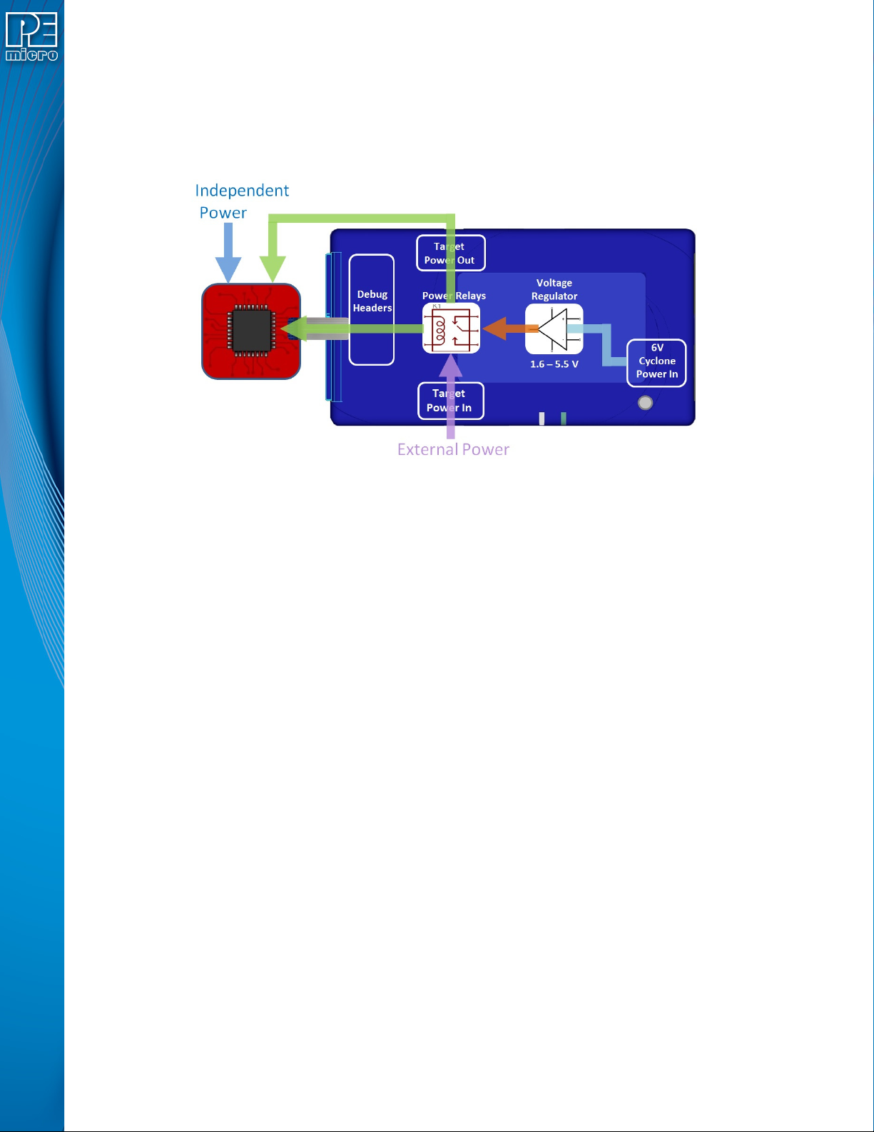
4 TARGET POWER MANAGEMENT
Different target devices may require different power schemes which depend on the design of the
target board, target voltages, and even the device architecture. PEmicro has designed the
Cyclone LC to be capable of powering a target before, during, and after programming. Power can
be sourced at many voltage levels from the Cyclone itself, or sourced by an external power supply
and switched by the Cyclone.
Figure 4-1: Five different paths to power a target
The versatility of the Cyclone power scheme gives the user the utmost flexibility, and includes the
following features:
• Provides power through a power jack or through the debug connector
• Provides internally generated voltage from 1.6v-5.5v at up to 500mA
• Switches an external power supply voltage, up to 24V at 1amp
• Selectively powers the target before, during, and after programming
• Powers down the target connections between programming operations
• Uses power switching to aid entry into debug mode for certain targets
• Provides target voltage and current measurement capabilities
If target power is required, each target board may vary where the power is sourced from, externally
or internally, and how it is channeled to the target: through the debug header or to a separate
connector to the board. Power that is passed through and managed by the Cyclone goes through
power relays so it can be power cycled. This is extremely useful because it also allows the power
to be off during setup and automatically powered on by the Cyclone for programming. For some
devices, the process of entering debug mode requires that the device be powered down and
powered back up. Power can also be left in a desired power state, either on or off.
4.1 Cyclone Configuration
There are two different places Power Management is configured and they should be matched:
first, by the jumpers on the Cyclone LC, and second, in the setup of the programming image.
The Cyclone jumpers are the most important because they are the physical connection to the
target. The Cyclone has an easy access panel that reveals debug header connections for a variety
of different architectures, and a 2x4 jumper block for configuring power management of the target.
The specific location of the jumpers is indicated by the label POWER JUMPERS in Figure 4-3.
This set of 4 jumpers can be used to set 5 different power management schemes for the target.