c900773.R02_EN.pdf - 第102页
4 Electrical Section 4-32 Electrodes on Feeder / Feeder Bank Tape feeder is able to run by receiving an electric signal from m achin e via feeder bank. When contact failure occurs between feeder bank and machi ne, tape f…

4 Electrical Section
4-31
Control Board
Handling Control Board
Note the followings when handling PC boards.
z Do not touch control boards by wet hands.
z Do not handle and place the control boards onto any place where any metal chips are around or easily
stick to the board.
z Before touching the board, wear an antistatic wrist strap and connect it with any metal part of the
machine.
z Do not handle and place the control boards to any place where short circuit may occur.
4 Electrical Section
4-32
Electrodes on Feeder / Feeder Bank
Tape feeder is able to run by receiving an electric signal from machine via feeder bank. When contact
failure occurs between feeder bank and machine, tape feeder may not run normally and steady, and it may
cause component pick-up error.
When electrodes on the feeder bank and the machine get dirty, clean them as follows:
NOTE: When the electrodes are touched by hand or have come into contact with foreign matter, cleaning is
recommended even if no dirt can be observed visually.
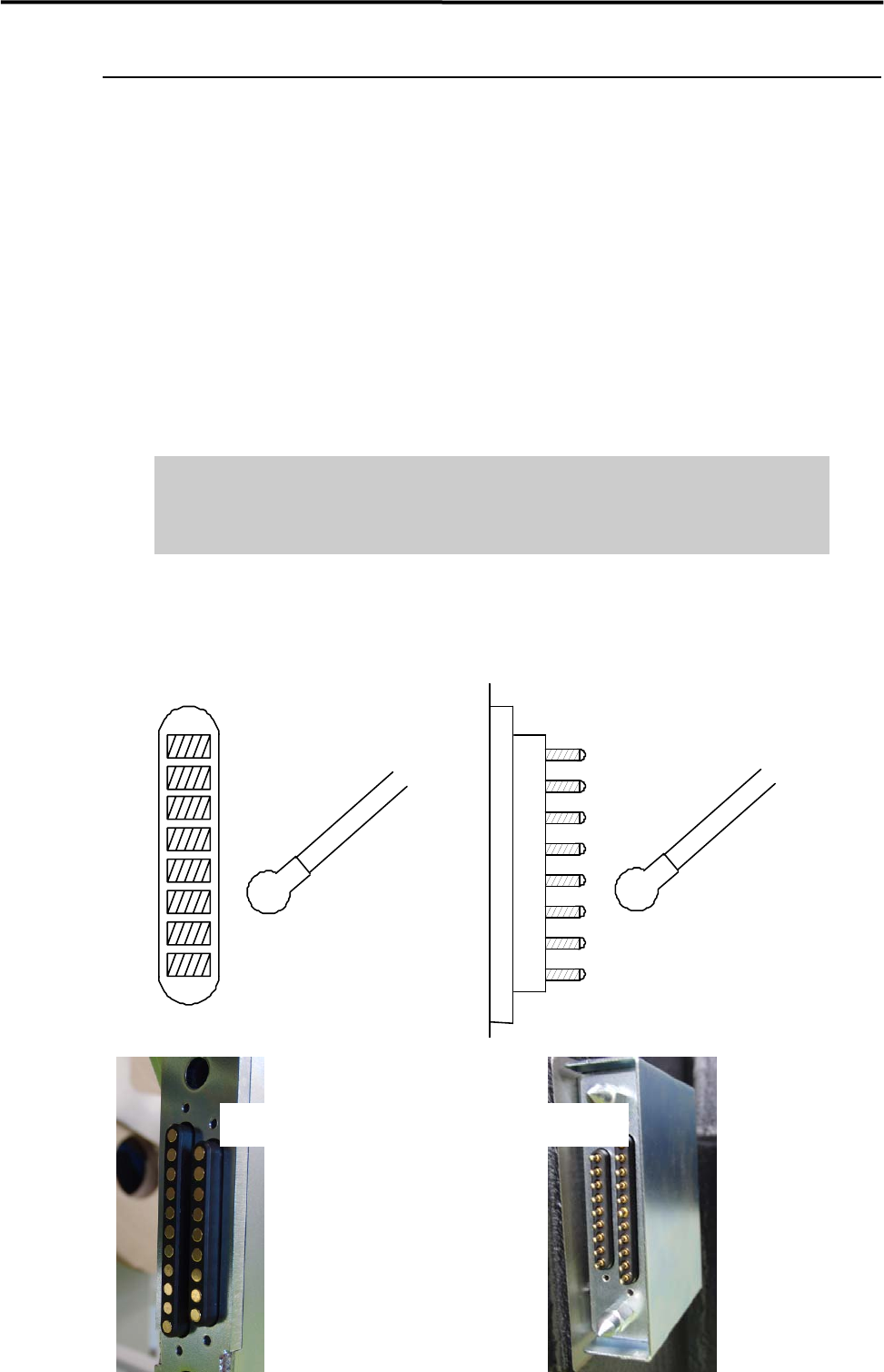
ACTION: Use a dry cotton swab or non-woven cloth and gently wipe off any dust on the electrodes. While cleaning
the electrodes, check and make sure that the pins on the electrodes are not bent. When it is found that the
pins are bent, contact us for repair. Continuing to use the tape feeder with its pins bent, pins may scratch the
contact surface of the feeder bank.
Do not use alcohol, water base detergents and organic solvent, such as
thinner, benzene and acetone.
Do not use sandpaper and tools with sharp blade or edge, such as a knife and
a screwdriver.
NOTE: When stubborn stains and dirt are on the electrodes, do not try getting rid of them forcedly. Please contact
us.
Cotton swab
Pin Elec tro de s on ma chineElectrodes on feeder bank
Cotton swab
CFB Side Machine Side
4 Electrical Section
4-33
Adjustment of Board Detection Sensors
This section explains how to adjust the sensitivity of the board detection sensors.
● LC6-M90H1-00X PHOTO SENSOR E3Z-D81 (OMRON)
z Entrance sensor
z Exit sensor
z Exit buffer arrival sensor
■ Adjusting Procedure
① Place a PCB on the conveyor belt in the direction as if it is place in an actual production operation.
② Turn the sensor’s sensitivity thumb nut counter-clockwise all the way toward “min” and set the
sensitivity to the minimum level.
*Turning the sensitivity thumb nut clockwise toward “max” increases the sensitivity and turning it
counter-clockwise toward “min” decreases the sensitivity.
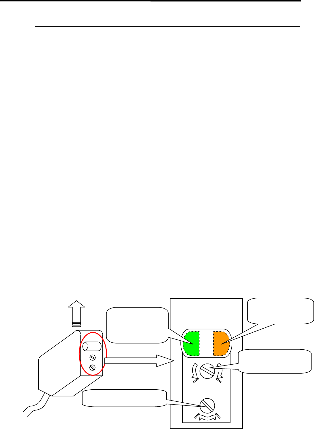
③ Slides the PCB along the conveyor belt and move it to above a target sensor. Turn the sensor’s
sensitivity thumb nut clockwise little by little toward “max” until the orange LED (operation
indicator) is lit. (This refers to (A) thereafter.)
④ Remove the PCB and turn the sensitivity thumb nut clockwise toward “max” until the orange LED is
lit. (This refers to (B) thereafter.) If the orange LED is not lit even though the sensitivity thumb nut is
turned all the way toward “max”, keep the thumb nut at far end on “max”. (In such case, this also
considered as and refers to (B) thereafter.)
⑤ Set the mid point between (A) and (B) as the adjustment position of the sensitivity thumb nut.
Once the adjustment position is fixed, check to make sure that both orange LED and green LED are lit
when a PCB is placed to above the sensor, and only the green LED is lit when the PCB is removed.
⑥ When the conveyor cover is provided because of the safety spec., attach a black rubber sheet to the
sensor detection position on the bottom of the cover to prevent false detection.
NOTE: Make sure that the operation selector switch is set to “L” (ON when light is entered).
max min
DL
Sensor emitting direction
Large View of Sensor
Operation indicator
(Orange LED)
Operation-stable
indicator
(Green LED)
Sensitivity thumb nut
Operation selector switch