c900773.R02_EN.pdf - 第26页
1 Installation 1-12 NOTE: The hydraulic jacks must satisfy the following requirem ents. Allowable load: 1.5 tons or hi gher Hook size: 100mm or more (st roke) Part Name Part No. Remark PLATE,BASE LG0-M8911-00X For plates…
1 Installation
1-11
Supplementary Explanation for Installation
When setting up a production line, level adjustment and line positioning of the mounter may be carried out
at the same time. However, to fine-adjust the mounter position with the mounter level, we recommends that
the mounter be roughly positioned to the production line first, and then be leveled and positioned accurately
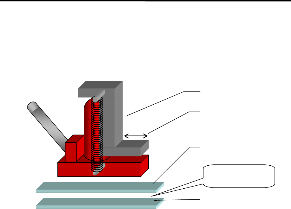
using the following four sets comprising a hydraulic jack and plates.
ACTION:
① Apply grease between base plates 1 and 2 for lubrication purposes.
② Place a plate set near each mounter jack-up point (four points).
③ Place a jack on each plate set and jack up the mounter.
④ Adjust each jack so that the mounter is level.
⑤ Fine-adjust the position of the mounter while the mounter is jacked up. (The mounter can be moved
lengthwise and crosswise with help of grease applied between the plates.)
Hydraulic jack
Base plate 1
Base plate 2
Apply grease
between the
p
lates.
Hook stroke
1 Installation
1-12
NOTE: The hydraulic jacks must satisfy the following requirements.
Allowable load: 1.5 tons or higher
Hook size: 100mm or more (stroke)
Part Name
Part No. Remark
PLATE,BASE LG0-M8911-00X For plates 1 and 2
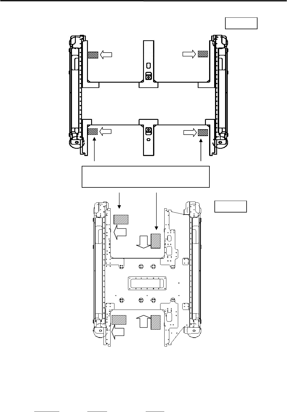
Jack -Up Points
Two Positions each at machine front and rear sides
M10
M20
1 Installation
1-13
Removal of Rust Inhibiting Grease
At packing and shipping, a large amount of grease is applied on the surface of each ball-screw and linear
guides on X/Y axes in order to prevent rust. As each axis moves an excess grease is gradually removed
from their surface and a proper amount of grease remains as a lubricant.
For this reason, when these axes are moved at installation, the extra grease may be built up on ball-screw
nuts, on linear guide sliders, and both ends of each axis. If you run the mounter at high speed (production)
without wiping it away, the grease may be scattered around due to centrifugal force and vibration, and that
may stick to cameras, sensors, or a board.
Please perform a warm-up at low speed once the origin is acquired after installation, and wipe off any
excess grease as necessary.
The mounter may not function properly when grease sticks to the sensors
and the cameras.
ACTION:
① Check and remove any board and tools from inside of the mounter, and then perform origin
acquisition.
② Select Main Menu> Manual> Warm Up.
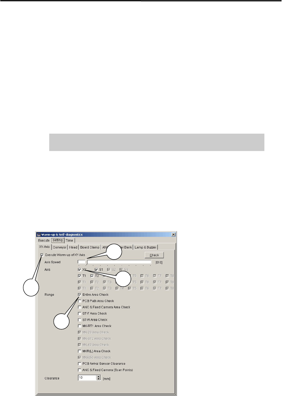
③ Select Warm-up & Self-diagnostics> Setting.
④ Select [XY-axes] and set up the parameters as follows.
1: Check “Execute Warm-up of XY-axes”.
2: Set “Axis Speed” at 10%.
3: Check “XY “.in Axis.
4: Check “Entire Area Check“in Range.
* It is not necessary to check other items.
3
1
2
4