c900773.R02_EN.pdf - 第76页
4 Electrical Section 4-6 Serial DO Map Turning on/off in the serial DO Map allow s an actuator to moves. Please be confirmed safety before exciting this function. ■ Device 1 Address Bit No. Signal Name Address Bit No. Si…
4 Electrical Section
4-5
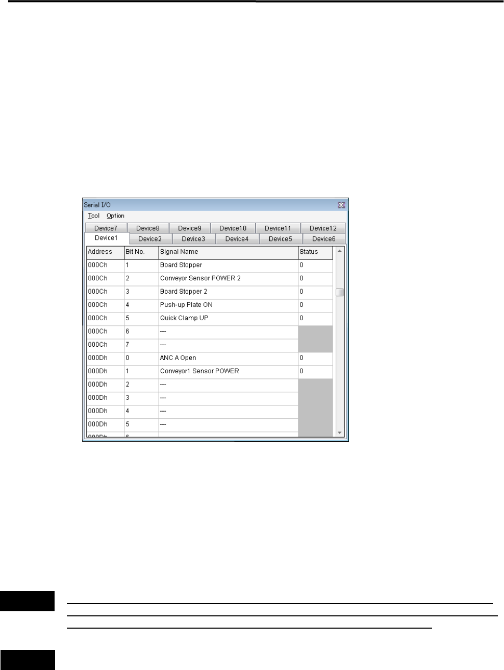
Serial I/O
■ Serial I/O List
Serial DO – Device 1, 3, 5, 7, 9, 11, 13, 15
Serial DI – Device 2, 4, 6, 8, 10, 12, 14, 16
Action:
① Click the cell of corresponding desired actuator.
② As the cell is clicked, the display changes 1(On) or 0(Off), and the actuator runs accordingly.
Example:
■ Moving Up and Down the Board Stopper
① Go to Manual > Signal I/O, and open the “Serial I/O” window.
② Select the [Device 1] tab.
③ Once the “Status” cell of “Board Stopper” is clicked, the status changes from “0” to “1” and the board
stopper goes up.
At this time, confirm that status of [PCB Stopper On] in the [Device 2] tab switches from “0” to “1”.
④ To move down the board stopper, click the “Status” cell of “Board Stopper” once again. The status
changes from “1” to “0” and the board stopper goes down. At this time, the status of [PCB Stopper On] in
the [Device 2] tab switches from “1” to “0”.
Turning on/off signal output in the Signal Output (Control) window allows an actuator to move. When
executing this operation, do not stick head, hands, or other parts of the body inside the mounter. Serious
injury may result. Also make sure non-operators are in a safe distance from the mounter.
Before performing signal output on/off operation, make sure no foreign obstacles are left in the mounter or
the tray feeder. Otherwise, costly machine damage can occur.
Warning
Caution
4 Electrical Section
4-6
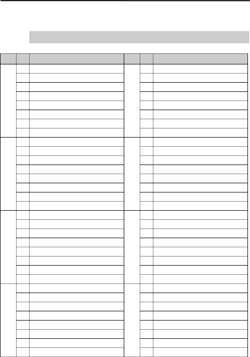
Serial DO Map
Turning on/off in the serial DO Map allows an actuator to moves.
Please be confirmed safety before exciting this function.
■ Device 1
Address
Bit
No.
Signal Name Address
Bit
No.
Signal Name
0000h 0 READY SW (F) 0004h 0
Signal Tower 1 On
1 RESET SW (F) 1
Signal Tower 2 On
2 START SW (F) 2
Signal Tower 3 On
3 STOP SW (F) 3
Signal Tower 4 On
4 CLEAR SW (F) 4
5 5
WARING SOUND
6 6
HAZARD SOUND
7 DOCKING SW (F) (Right Front) 7
UPS Shout down
0001h 0 DOCKING SW (Left Front) 0005h 0
READY Output
1 1
BOARD AVAILABLE Output
2 2
3 3
4 4
5 5
6 6 Trigger 1 Output Place Bit 0
7 7 Trigger 1 Output Place Bit 1
0002h 0 READY SW (R) 0006h 0
Safety Relay Rest
1 RESET SW (R) 1
Front Cover Lock
2 START SW (R) 2
Rear Cover Lock
3 STOP SW (R) 3
4 CLEAR SW (R) 4
5
5
Internal Illumination ON
6
6
SERVO ON Permission 1
7 DOCKING SW (Left Rear) 7
SERVO ON permission 2
0003h 0 DOCKING SW (R) (Right Rear) 0008h 0
Feeder Bank Board Power Supply (F) (Right Front )ON
1
1
Feeder Bank Board Power Supply (Left Front) ON
2
2
Feeder Bank Power (Right Front) 5V ON
3
CTF(Left Rear) Servo Power Supply
3
Feeder Bank Power (Left Front) 5V ON
4 CTF(R)(Right Rear) Servo Power Supply 4 Feeder Bank Power Supply (F) (Right Front) 24V ON
5 5 Feeder Bank Power (Left Front) 24V ON
6 6 Feeder Bank Board Power Supply (Left Rear) ON
7 7 Feeder Bank Board Power Supply (R) (Right Rear ON
4 Electrical Section
4-7
Address
Bit
No.
Signal Name Address
Bit
No.
Signal Name
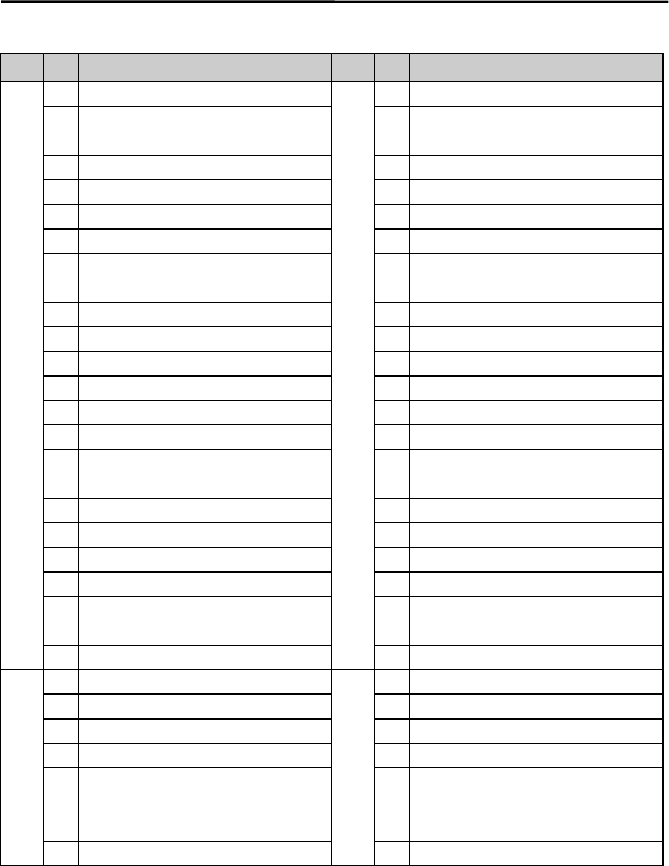
0009h 0
Feeder Bank Power (Left Rear) 5V ON
000Eh 0
Conveyor1 Alarm Reset
1
Feeder Bank Power (Right Rear) 5V ON
1
Conveyor2 Alarm Reset
2
Feeder Bank Power (Left Rear) 24V ON
2
Conveyor3 Alarm Reset
3
Feeder Bank Power Supply ® (Right Rear) 24V ON
3
4
Tape Cutter Open (F)
4
5
AMF Vacuum Stage / Tape Cutter Close (F)
5
Conveyor1 Rotation Direction
6
Tape Cutter Open (R)
6
Conveyor2 Rotation Direction
7
Tape Cutter Close (R)
7
Conveyor3 Rotation Direction
000Ah 0
CFB (F)/(Right Front) Unlock
000Fh 0
1
CFB (Left Front) Unlock
1
Conveyor1 Rotation
2
CFB (Left Rear) Unlock
2
Conveyor2 Rotation
3
CFB (R)/(Right Rear) Unlock
3
Conveyor3 Rotation
4
ACTIVE SW (F)
4
5
5
6
ACTIVE SW (R)/CTF(Left Rear)Draw-in Cylinder ON
6
7
CTF (Right Rear) Draw-in Cylinder ON
7
000Ch 0
0010h 0 Conveyor1 Speed Data Bit0
1
Board Stopper
1 Conveyor1 Speed Data Bit1
2
Conveyor Sensor POWER 2
2 Conveyor1 Speed Data Bit2
3
PCB L Stopper
3 Conveyor1 Speed Data Bit3
4
Push-up Plate ON
4 Conveyor1 Speed Data Bit4
5
Quick Clamp UP
5 Conveyor1 Speed Data Bit5
6
6 Conveyor1 Speed Data Bit6
7
7 Conveyor1 Speed Data Bit7
000Dh 0
ANC A Open
0011h 0 Conveyor2 Speed Data Bit0
1
Conveyor1 Sensor POWER
1 Conveyor2 Speed Data Bit1
2
2 Conveyor2 Speed Data Bit2
3
START SW (U-turn Conveyor)
3 Conveyor2 Speed Data Bit3
4
PCB Vacuum
4 Conveyor2 Speed Data Bit4
5
PCB Vacuum Break
5 Conveyor2 Speed Data Bit5
6
6 Conveyor2 Speed Data Bit6
7
7 Conveyor2 Speed Data Bit7