c900773.R02_EN.pdf - 第75页
4 Electrical Section 4-5 Serial I/O ■ Serial I/O List Serial DO – Device 1, 3, 5, 7, 9, 11, 13, 15 Serial DI – Device 2, 4, 6, 8, 10, 12, 14, 16 Action: ① Click the cell of corresponding desired act uator. ② As the cell …
4 Electrical Section
4-4
Signal Output Control
The status of each actuator (ON and OFF) can be changed through Signal Output Control. “1” indicates
that the actuator is ON, and “0” indicates OFF. Once “0” on the window is clicked, it changes “1”. Once
“1” is clicked, it changes to “0”. When “0” changes to “1” or “1” changes to “0”, the corresponding
actuator turns ON and OFF simultaneously. When trouble occurs, operating Signal Output Control can be
used for troubleshooting and to check to see whether an actuator functions normally or malfunctions.
Besides this, an actuator runs by operating Signal Output Control and sensor detects it, the outcome (ON
and OFF) is displayed on Signal Input Monitor.
The combination of an address and bit number (0-7) represents a signal. The name of each signal is shown
in the “Details” tab.
Turning on/off signal output in the Signal Output (Control) window allows an actuator to move. When
executing this operation, do not stick head, hands, or any other parts of the body inside the mounter. It may
result in serious injury. Also make sure non-operators are in a safe distance from the mounter.
Before performing signal output on/off operation, make sure no foreign obstacles are left in the mounter or
the tray feeder. Otherwise, costly machine damage may occur.
Menu: Manual>Signal I/O>Signal Output(Control)
■Digital Output (List) ・・・Not Use
■Digital Output (Details)・・・Not Use
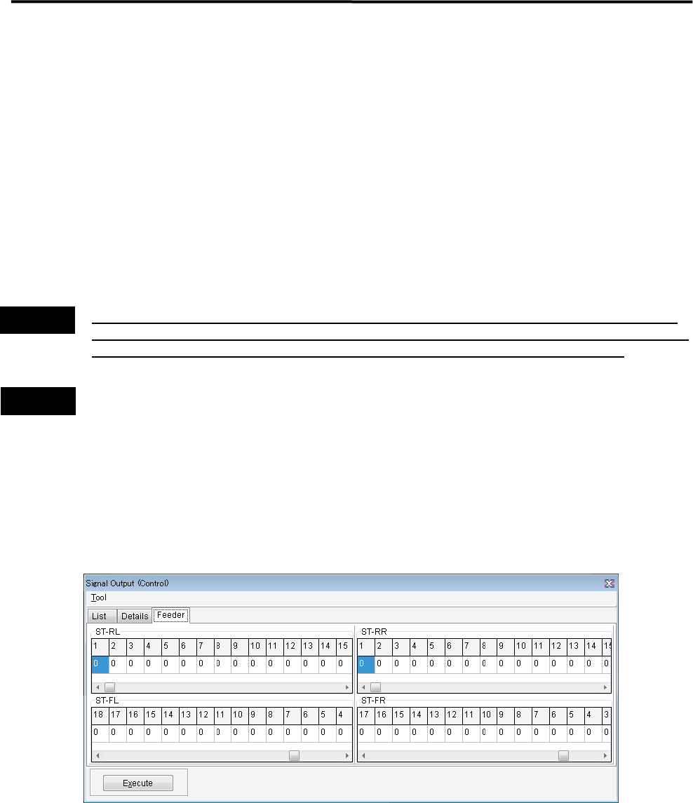
■ Feeder
It is possible to operate feeders set on the front and rear feeder banks.
Action:
① Slide the scroll bar to the left or right to display the desired feeder number.
② Click “0” of the desired feeder number. “0”changes to “1”.
③ Clicking the <Execute> button allows the feeder to feed a component.
Warning
Caution
4 Electrical Section
4-5
Serial I/O
■ Serial I/O List
Serial DO – Device 1, 3, 5, 7, 9, 11, 13, 15
Serial DI – Device 2, 4, 6, 8, 10, 12, 14, 16
Action:
① Click the cell of corresponding desired actuator.
② As the cell is clicked, the display changes 1(On) or 0(Off), and the actuator runs accordingly.
Example:
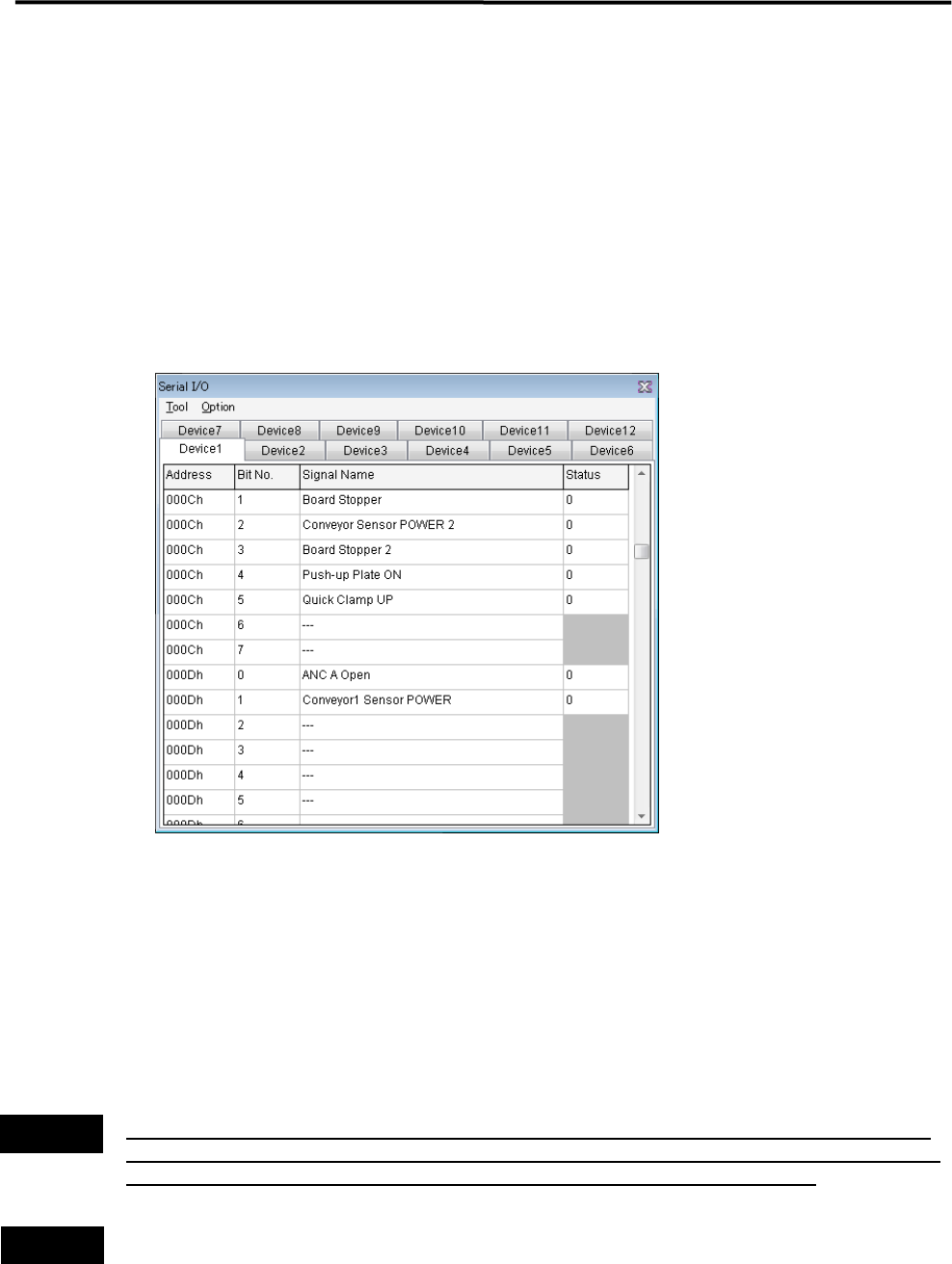
■ Moving Up and Down the Board Stopper
① Go to Manual > Signal I/O, and open the “Serial I/O” window.
② Select the [Device 1] tab.
③ Once the “Status” cell of “Board Stopper” is clicked, the status changes from “0” to “1” and the board
stopper goes up.
At this time, confirm that status of [PCB Stopper On] in the [Device 2] tab switches from “0” to “1”.
④ To move down the board stopper, click the “Status” cell of “Board Stopper” once again. The status
changes from “1” to “0” and the board stopper goes down. At this time, the status of [PCB Stopper On] in
the [Device 2] tab switches from “1” to “0”.
Turning on/off signal output in the Signal Output (Control) window allows an actuator to move. When
executing this operation, do not stick head, hands, or other parts of the body inside the mounter. Serious
injury may result. Also make sure non-operators are in a safe distance from the mounter.
Before performing signal output on/off operation, make sure no foreign obstacles are left in the mounter or
the tray feeder. Otherwise, costly machine damage can occur.
Warning
Caution
4 Electrical Section
4-6
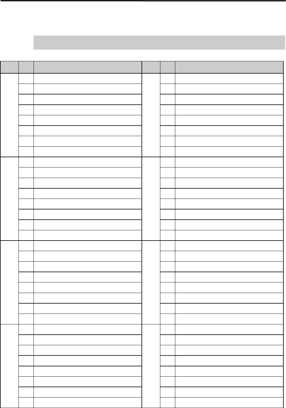
Serial DO Map
Turning on/off in the serial DO Map allows an actuator to moves.
Please be confirmed safety before exciting this function.
■ Device 1
Address
Bit
No.
Signal Name Address
Bit
No.
Signal Name
0000h 0 READY SW (F) 0004h 0
Signal Tower 1 On
1 RESET SW (F) 1
Signal Tower 2 On
2 START SW (F) 2
Signal Tower 3 On
3 STOP SW (F) 3
Signal Tower 4 On
4 CLEAR SW (F) 4
5 5
WARING SOUND
6 6
HAZARD SOUND
7 DOCKING SW (F) (Right Front) 7
UPS Shout down
0001h 0 DOCKING SW (Left Front) 0005h 0
READY Output
1 1
BOARD AVAILABLE Output
2 2
3 3
4 4
5 5
6 6 Trigger 1 Output Place Bit 0
7 7 Trigger 1 Output Place Bit 1
0002h 0 READY SW (R) 0006h 0
Safety Relay Rest
1 RESET SW (R) 1
Front Cover Lock
2 START SW (R) 2
Rear Cover Lock
3 STOP SW (R) 3
4 CLEAR SW (R) 4
5
5
Internal Illumination ON
6
6
SERVO ON Permission 1
7 DOCKING SW (Left Rear) 7
SERVO ON permission 2
0003h 0 DOCKING SW (R) (Right Rear) 0008h 0
Feeder Bank Board Power Supply (F) (Right Front )ON
1
1
Feeder Bank Board Power Supply (Left Front) ON
2
2
Feeder Bank Power (Right Front) 5V ON
3
CTF(Left Rear) Servo Power Supply
3
Feeder Bank Power (Left Front) 5V ON
4 CTF(R)(Right Rear) Servo Power Supply 4 Feeder Bank Power Supply (F) (Right Front) 24V ON
5 5 Feeder Bank Power (Left Front) 24V ON
6 6 Feeder Bank Board Power Supply (Left Rear) ON
7 7 Feeder Bank Board Power Supply (R) (Right Rear ON