c900773.R02_EN.pdf - 第24页
1 Installation 1-10 Air and Power Cable Lead-In Air Regulator 0.45MPa Air Coupler Supply Side Air Coupler 65SN/85SN (NITTO KOHKI) Corresponding Goods The power cable terminal block is located at inside of the right lower…
1 Installation
1-9
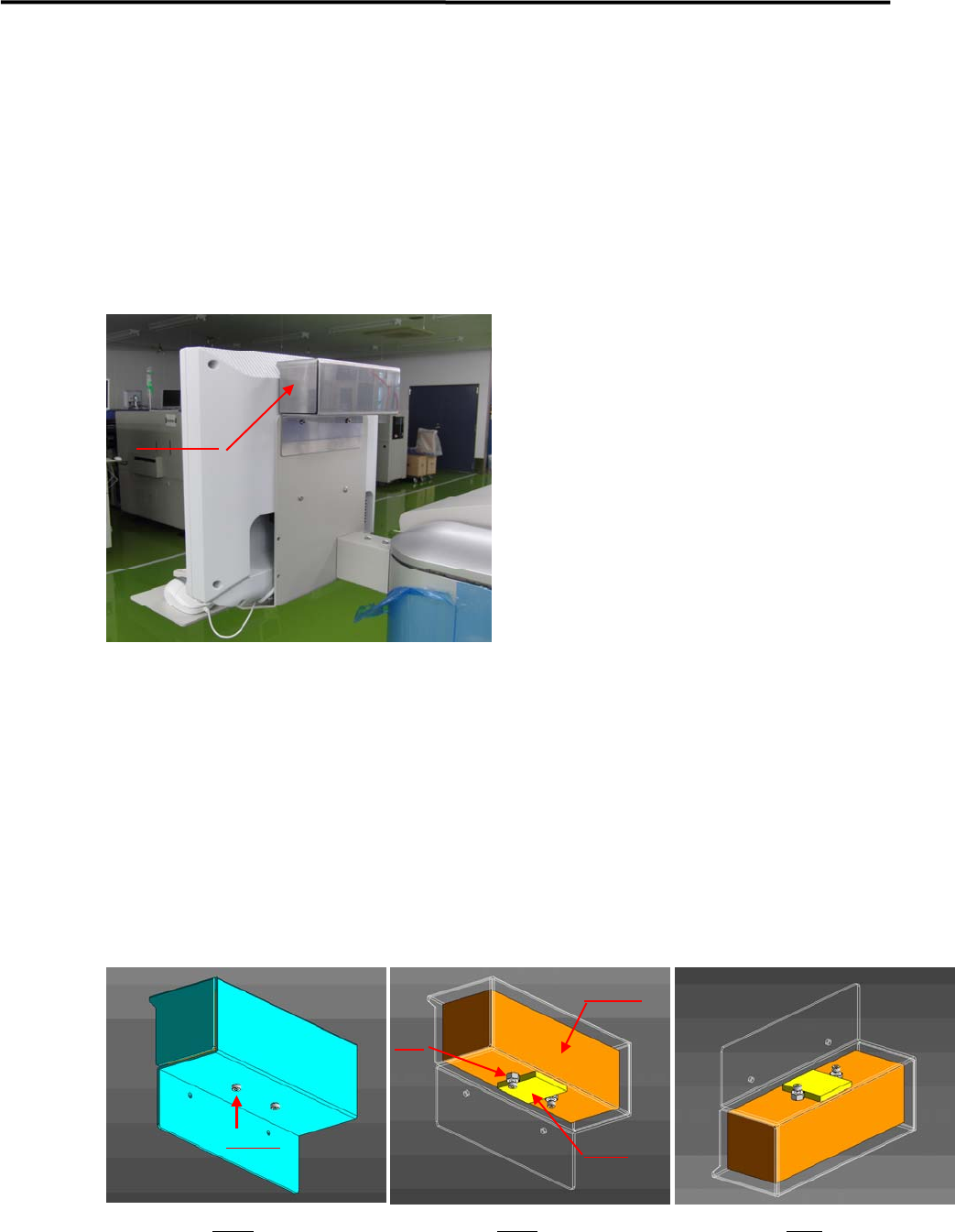
LCD Monitor and Installation of Balancer
A balancer is put on LCD monitor to prevent the monitor from vibrating. It is removed and a weight inside
the balancer is fixed, and then is packaged separately before shipment.
In the machine installation, it should be confirmed that the weight has been unfixed before installing the
balancer on the monitor.
Details of Installation
① A balancer is installed on the back of Monitor (refer to the above picture ).
② Fig.1 shows a balancer unit.
③ A weight is inside of the balancer unit , which is attached on the plate by GOM (Fig.2).
④ A weight is fixed by screws and nuts before shipment ( Fig.2).
⑤ Before setting the balancer, screws and nuts have to be removed.
Remark; the balancer should not be turned upside down when removing screws and nut (Fig.3),
otherwise it may drop off.
Balancer
Fig 1 Fig 2 Fig3
Screws
Nut
Weight
GOM
1 Installation
1-10
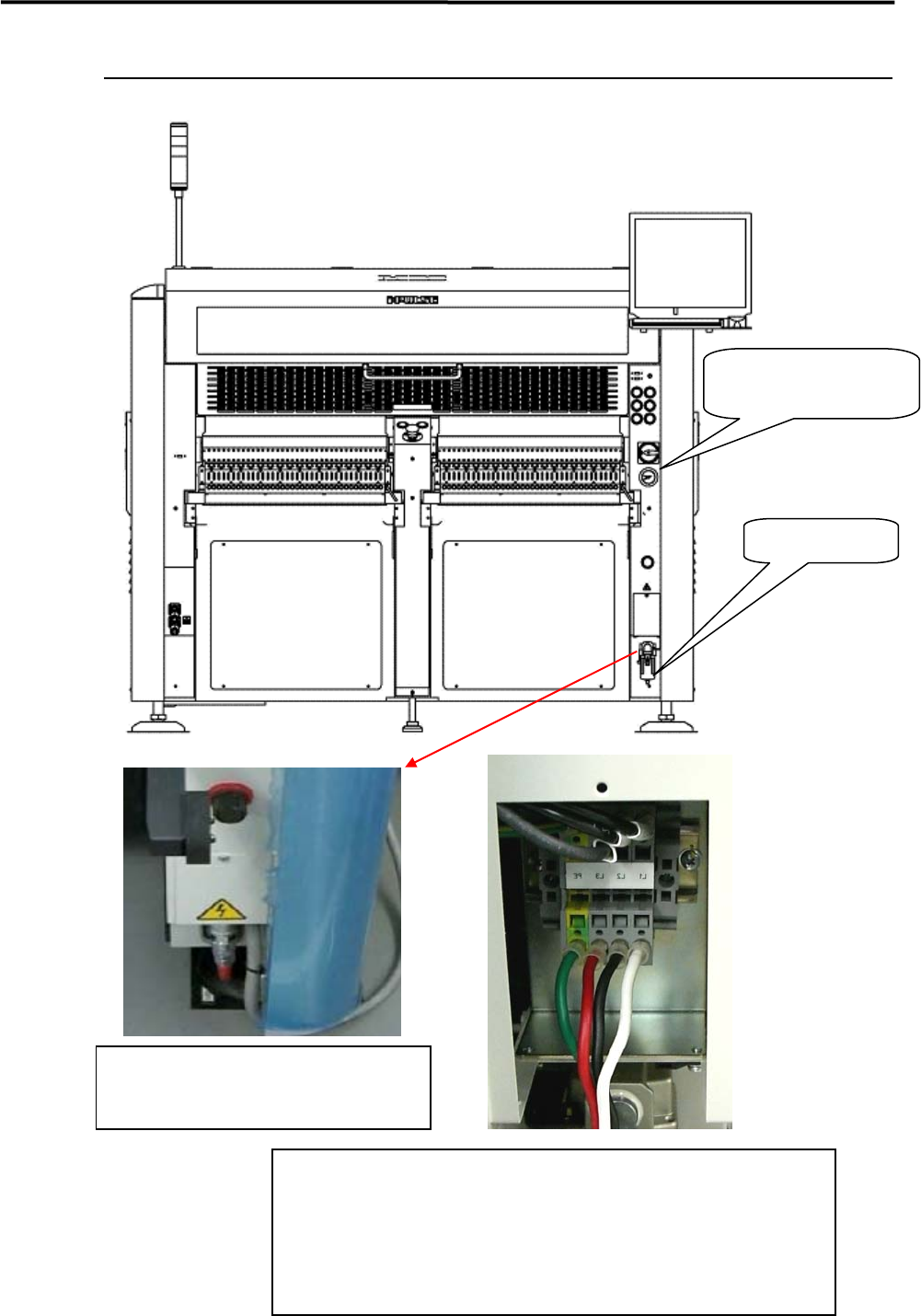
Air and Power Cable Lead-In
Air Regulator
0.45MPa
Air Coupler
Supply Side Air Coupler
65SN/85SN
(NITTO KOHKI)
Corresponding Goods
The power cable terminal block is located at
inside of the right lower cover, so the cover has to
be opened , then power cables are connected to
the block.
Electric Power Supply Source
Source Voltage: AC200/208/220/240/380/400/416/440V
Three Phase 50/60Hz
Current Capacity: 6.0kV
Electric Wire:VCT 3.5mm2 or more, Four-cores cables
Terminal:Insulating Pin Terminal
TMEV TC3.5-11(made by NITHIFU) or similar
p
roducts
1 Installation
1-11
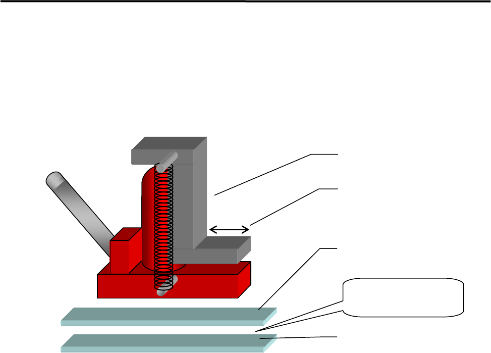
Supplementary Explanation for Installation
When setting up a production line, level adjustment and line positioning of the mounter may be carried out
at the same time. However, to fine-adjust the mounter position with the mounter level, we recommends that
the mounter be roughly positioned to the production line first, and then be leveled and positioned accurately
using the following four sets comprising a hydraulic jack and plates.
ACTION:
① Apply grease between base plates 1 and 2 for lubrication purposes.
② Place a plate set near each mounter jack-up point (four points).
③ Place a jack on each plate set and jack up the mounter.
④ Adjust each jack so that the mounter is level.
⑤ Fine-adjust the position of the mounter while the mounter is jacked up. (The mounter can be moved
lengthwise and crosswise with help of grease applied between the plates.)
Hydraulic jack
Base plate 1
Base plate 2
Apply grease
between the
p
lates.
Hook stroke