c900773.R02_EN.pdf - 第98页
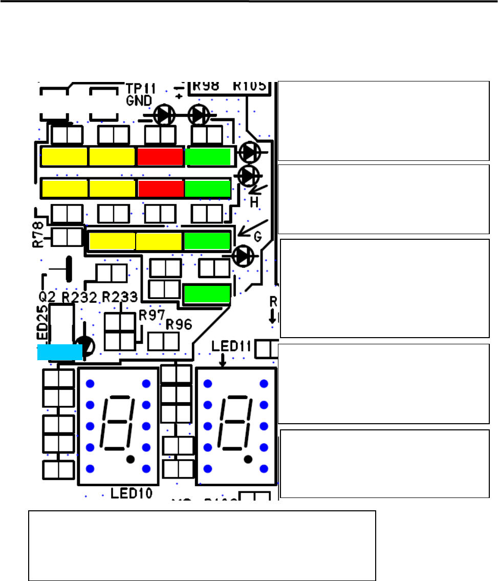
4 Electrical Section 4-28 Motion Operation Check LED LED6 LED9 LED8 LED7 LED4 LED5 LED3 LED20 LED22 LED24 LED21 LED23 LED25 If ATX power supply voltage is normal, t he following LEDs will be lit . LED6 +5V Standby LED9 +…
4 Electrical Section
4-27
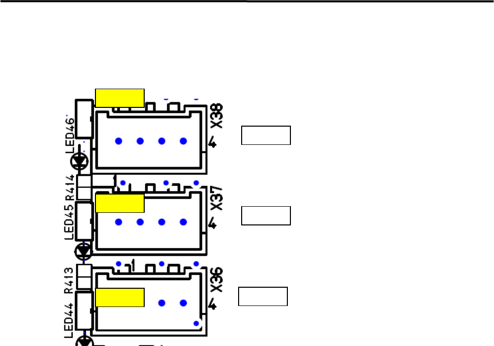
Motion Port Operation Check LED
z LED44 Port 0 (X, Y Axis) and 45 Port 1 (Z, T Axis) will be lit (Yellow) when receiving response data
from the servo amplifiers.
LED46
LED45
LED44
Port2
Port1
Port0
CTF
Z & T Axes
X&Y Axes
4 Electrical Section
4-28
Motion Operation Check LED
LED6
LED9
LED8
LED7
LED4
LED5
LED3
LED20
LED22
LED24
LED21
LED23
LED25
If ATX power supply voltage is normal, the
following LEDs will be lit .
LED6 +5V Standby
LED9 +3.3V
LED8 +5V
LED7 +12V
LED4 (Red) will be lit in power saving mode.
LED5 (Red) will be lit when temperature of
CPU module is abnormal.
LED 3(Yellow) will be lit when accessing HDD
Loading data to each FPGA has been
succeeded and communication has been
established to PCI Express Vision
Motion after power on, below LEDs will
be lit.
LED20 Vision
LED22 Motion
LED24 Serial I/O
Below LEDs will be lit (Yellow) during DMA
transfer
LED21;Vision , Vision Data DMA
LED23; Motion, Axes Data DMA
*Note; LED23 looks like being lit when the
system has been booted up normally.
LED25 (Blue)
LED25 (Blue) will be blinked quickly when the
system runs normally.
LED25 (Blue) is lit or blackout when the system
is in abnormal state.
Seven Segment LED; LED10 – High Order, LED11-Low Order
After Windows has booted up normally, “c0” will be shown on the seven
segments. Details of other cods shown in the seven segments are described on the
next page.

4 Electrical Section
4-29
The detail of 7 segments LED indications is shown in the below table.
Diagnostic
Code
Meaning
Diagnostic
Code
Meaning
02h Verify processor mode 41h Initialize extended memory for Rom Pilot
03h Disable Non-Maskable Interrupt (NMI) 42h Initialize interrupt vectors
04h Get CPU type 45h POST device initialization
06h Initialize system hardware 46h Check ROM copyright notice
07h Disable shadow and execute code from the ROM. 47h Initialize I2O support
08h Initialize chipset with initial POST values 48h Check video configuration against CMOS
09h Set IN POST flag 49h Initialize PCI bus and devices
0Ah Initialize CPU registers 4Ah Initialize all video adapters in system
0Bh Enable CPU cache 4Bh QuietBoot start
0Ch Initialize caches to initial POST values 4Ch Shadow video BIOS ROM
0Eh Initialize I/O components 4Eh Display BIOS copyright notice
0Fh Initialize the local bus IDE 4Fh Initialize MultiBoot
10h Initialize Power Management 50h Display CPU type and speed
11h Load alternate registers with initial POST values 51h Initialize EISA board
12h Restore CPU control word during warm boot 52h Test keyboard
13h Initialize PCI Bus Mastering devices 54h Set key click if enabled
14h Initialize keyboard controller 55h Enable USB devices
16h BIOS ROM checksum 58h Test for unexpected interrupts
17h Initialize cache before memory autosize 59h Initialize POST display service
18h 8254 timer initialization 5Ah Display prompt "Press F2 to enter SETUP"
1Ah 8237 DMA controller initialization 5Bh Disable CPU cache
1Ch Reset Programmable Interrupt Controller 5Ch Test RAM between 512 and 640 KB
20h Test DRAM refresh 60h Test extended memory
22h Test 8742 Keyboard Controller 62h Test extended memory address lines
24h Set ES segment register to 4 GB 64h Jump to UserPatch1
28h Auto size DRAM 66h Configure advanced cache registers
29h Initialize POST Memory Manager 67h Initialize Multi Processor APIC
2Ah Clear 512 KB base RAM 68h Enable external and CPU caches
2Ch RAM failure on address line xxxx 69h Setup System Management Mode (SMM) area
2Eh RAM failure on data bits xxxx of low byte of memory
bus
6Ah
Display external L2 cache size
2Fh Enable cache before system BIOS shadow 6Bh Load custom defaults
32h Calculate CPU speed 6Ch Display shadow-area message
33h Initialize POST Dispatch Manager 6Eh Display possible high address for UMB recovery
34h Test CMOS RAM and RTC 70h Display error messages
36h Initialize shut down victor for warm start 72h Check for configuration errors
38h Shadow system BIOS ROM 76h Check for keyboard errors
3Ah Autosize cache 7Ch Set up hardware interrupt vectors for 08-0F and 70-77
3Ch Advanced configuration of chipset registers 7Dh Initialize Intelligent System Monitoring
3Dh Load alternate registers with CMOS values 7Eh Initialize coprocessor if present