c900773.R02_EN.pdf - 第20页
1 Installation 1-6 ACTION: ① Locate the mounter to the specified place. ② Remove the followings: the b olt that locks the h ead in the X-axis beam and the metal fitting th at prevent X-axis beam movement to the Y directi…
1 Installation
1-5
Installing Mounter
Do not touch terminals of electric components when the power is on to prevent electric shock and mounter
damage.
Make sure to ground the mounter to prevent electric shock.
Note on Installation
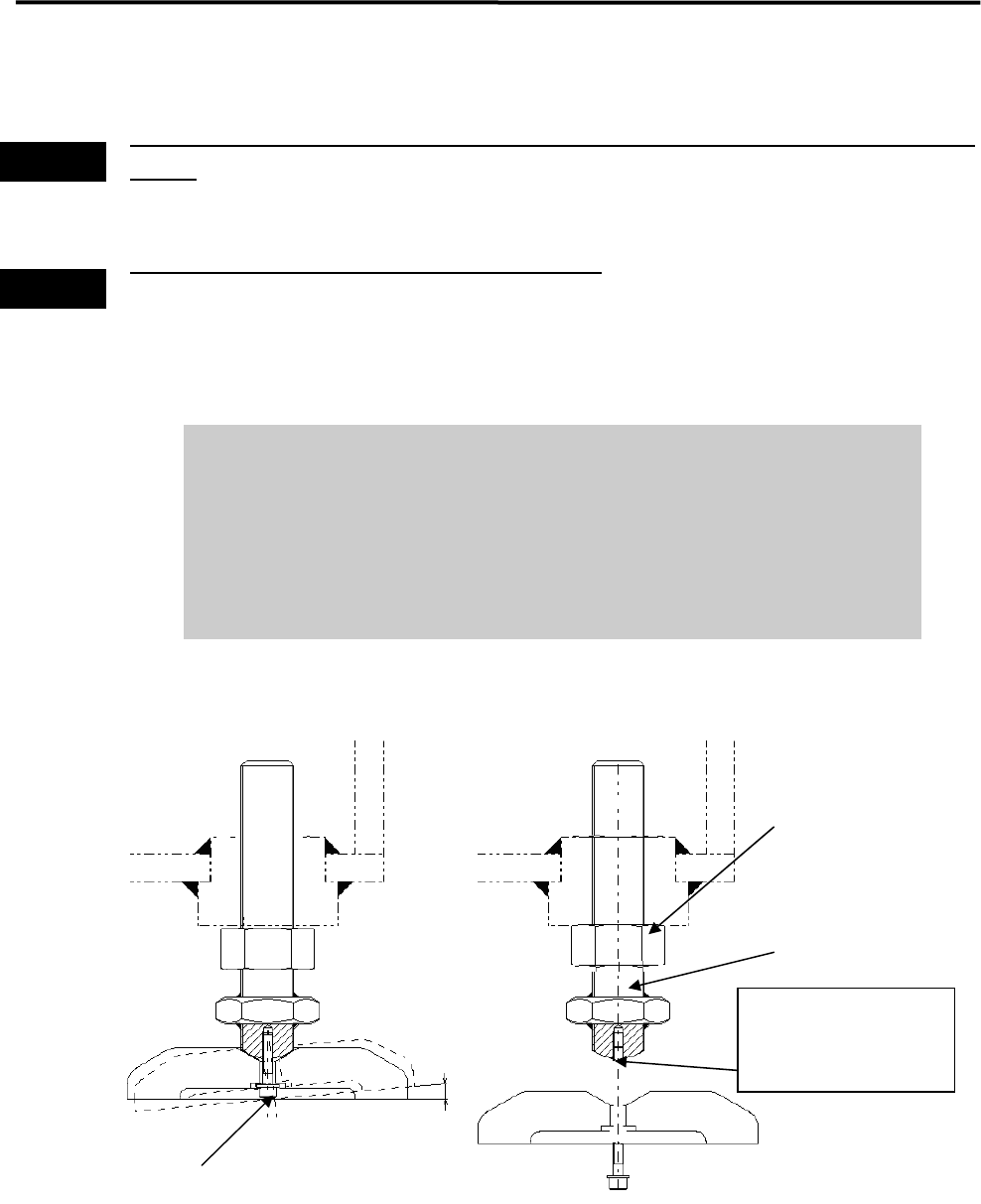
It is normal that the adjust foot can be slightly inclined (within 2-degree range).
Do not tighten the bolt forcedly trying to fix the foot.
When you move and/or install the mounter, be careful not to apply excessive
force on the adjust foot. This may cause the screw of the adjust foot to break.
When placing the mounter on the floor, be sure that the mounter is kept
horizontal.
Warning
Warning
2°
If excessive force is
applied, the screw may
break at this point.
Mounting Screw
Nut
Adjust foot
1 Installation
1-6
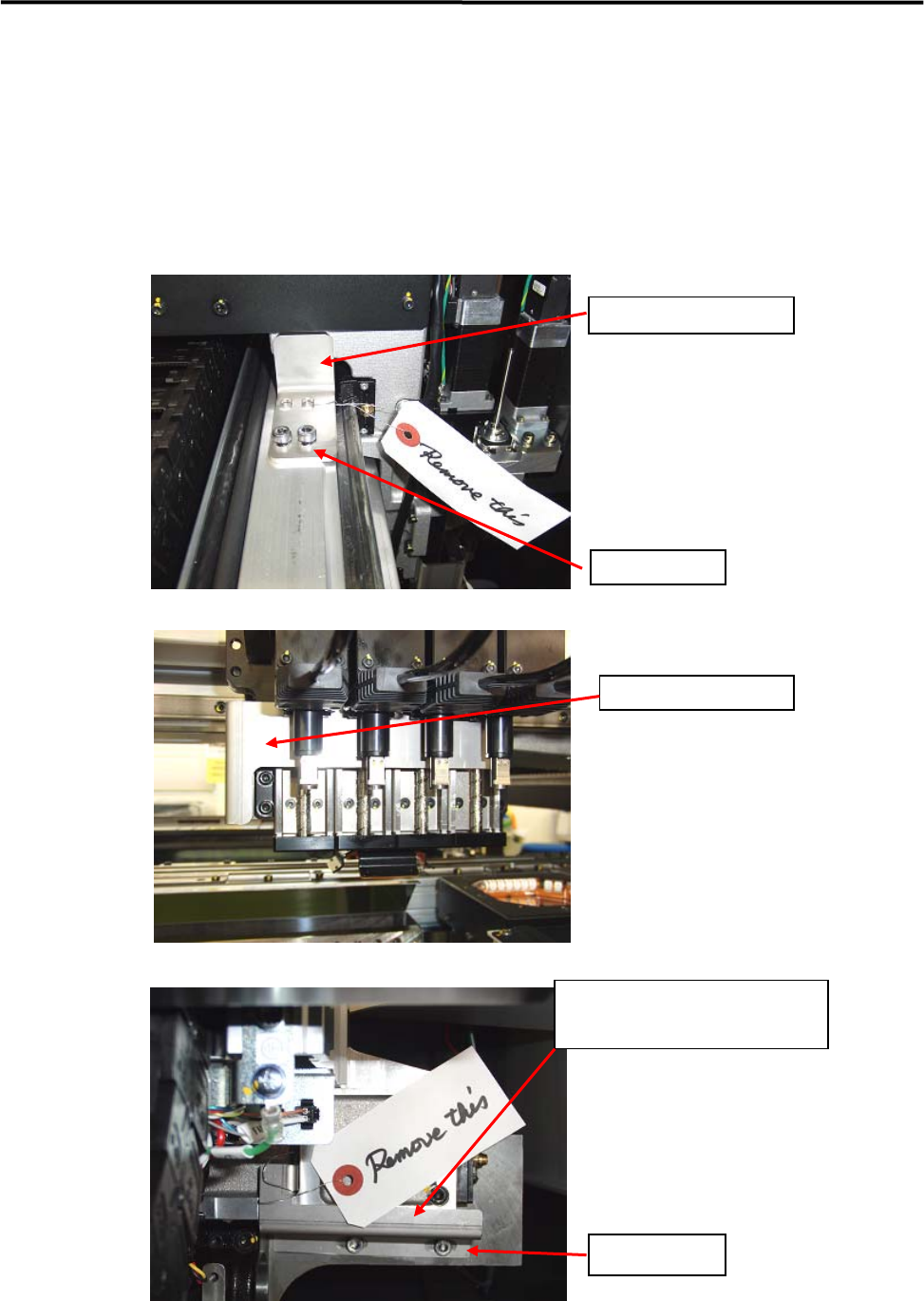
ACTION:
① Locate the mounter to the specified place.
② Remove the followings: the bolt that locks the head in the X-axis beam and the metal fitting that
prevent X-axis beam movement to the Y direction. After removed the bolts and fittings, confirm that
the head can move to the X direction and the X-axis beam can move to the Y direction manually.
Note; Please keep the bolts and metal fittings, they will be necessary if moving the machine.
X Axis Fixing Bracket
Fixing Screw
Head Fixing Bracket
Y Axis Fixing Bracket
(two brackets at both sides)
Fixing Screws
1 Installation
1-7
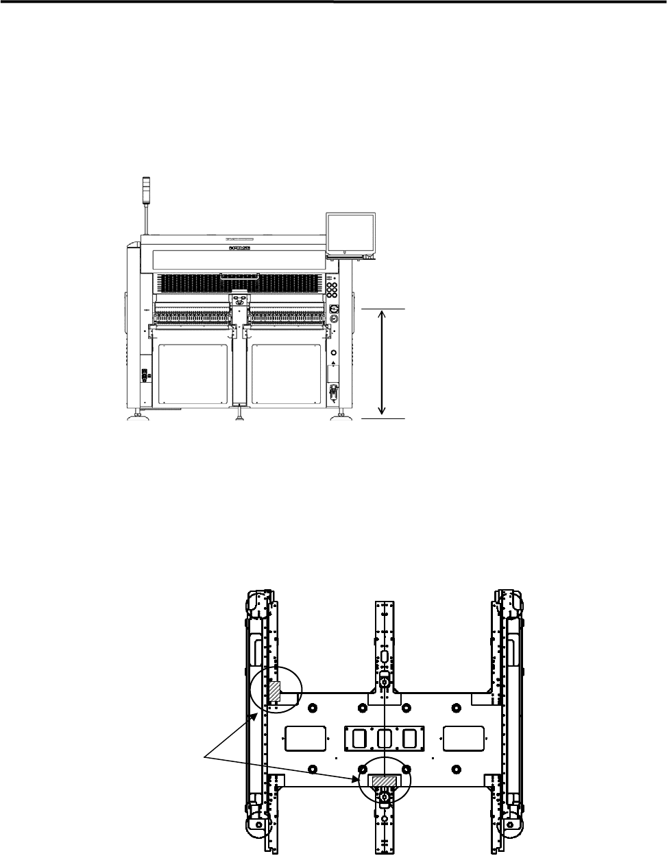
③ When the mounter is installed stand alone, turn the adjust feet so that the PCB transfer height is the
same as the conveyor height (900±20mm (see Note)) of the reference equipment.
When the mounter is connected to the Pre-process on production line, adjust the PCB transfer height
to the conveyor rail height of the Pre-process.
)
Production Line
In the case of SMEMA interface spec, the height must be 950±20mm.
900±20mm
または、
950±20mm(SMEMA 規格)
NOTE: The height must be 890 to 920mm in the case of CFB wagon spec.
NOTE: The adjust feet must be turned using a M30 single-head wrench (nominal: 46mm).
④ Place a leveler on the base of the mounter. Set the position to the conveyor of the Pre-process finely
until the mounter is leveled.
) Supplementary Explanation for Installation
⑤ After the mounter is positioned, make sure that a board runs smoothly between upstream and
downstream conveyor.
⑥ Place a leveler on the X-axis beam and make a fine adjustment so that the difference in indicator when
the X-axis beam moves forward and backward will be within 1 division. ( To prevent a X-axis beam
distortion. )
Ll
Levers