c900773.R02_EN.pdf - 第22页
1 Installation 1-8 Viewed from the front Viewed from the rear ⑦ Lock the adjust foo t nut lastly. NOTE: The adjust foot nuts must be locked with a clos ed wrench (nom inal: 46mm ) or a single-head wrench. ⑧ Connect the p…
1 Installation
1-7
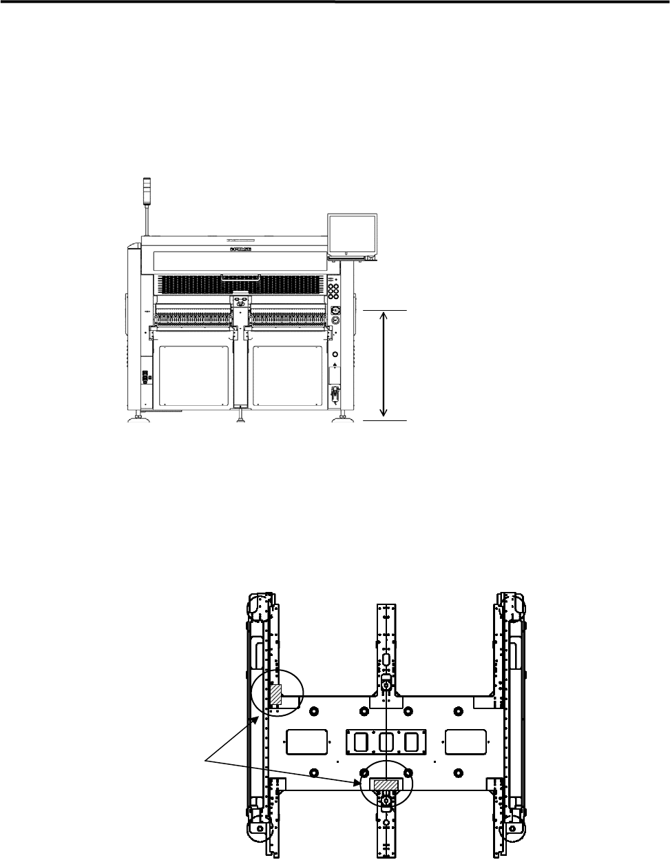
③ When the mounter is installed stand alone, turn the adjust feet so that the PCB transfer height is the
same as the conveyor height (900±20mm (see Note)) of the reference equipment.
When the mounter is connected to the Pre-process on production line, adjust the PCB transfer height
to the conveyor rail height of the Pre-process.
)
Production Line
In the case of SMEMA interface spec, the height must be 950±20mm.
900±20mm
または、
950±20mm(SMEMA 規格)
NOTE: The height must be 890 to 920mm in the case of CFB wagon spec.
NOTE: The adjust feet must be turned using a M30 single-head wrench (nominal: 46mm).
④ Place a leveler on the base of the mounter. Set the position to the conveyor of the Pre-process finely
until the mounter is leveled.
) Supplementary Explanation for Installation
⑤ After the mounter is positioned, make sure that a board runs smoothly between upstream and
downstream conveyor.
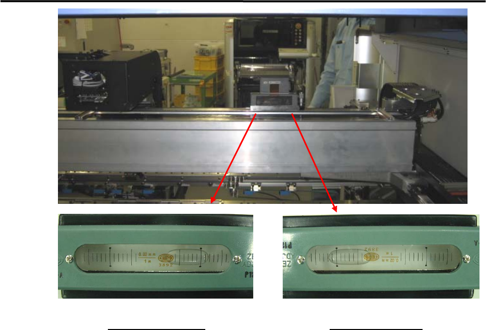
⑥ Place a leveler on the X-axis beam and make a fine adjustment so that the difference in indicator when
the X-axis beam moves forward and backward will be within 1 division. ( To prevent a X-axis beam
distortion. )
Ll
Levers
1 Installation
1-8
Viewed from the front
Viewed from the rear
⑦ Lock the adjust foot nut lastly.
NOTE: The adjust foot nuts must be locked with a closed wrench (nominal: 46mm) or a single-head wrench.
⑧ Connect the power cable and ground line independently of other machines which may be a noise
source, such as a compressor, welding machine.
⑨ Connect an intake-side air coupler 65SN or 85SN (Nitto Kohki) or equivalent to the air regulator
coupler located on the rear of the mounter. After the coupler is connected, make sure that the air
regulator’s reading is 0.5MPa(5.1 ㎏ f/c ㎡).
1 Installation
1-9
LCD Monitor and Installation of Balancer
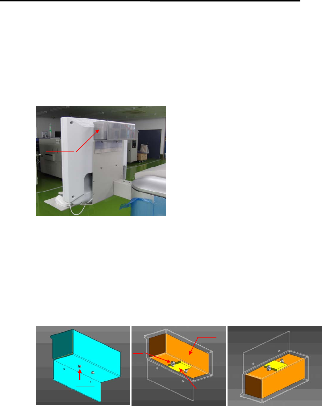
A balancer is put on LCD monitor to prevent the monitor from vibrating. It is removed and a weight inside
the balancer is fixed, and then is packaged separately before shipment.
In the machine installation, it should be confirmed that the weight has been unfixed before installing the
balancer on the monitor.
Details of Installation
① A balancer is installed on the back of Monitor (refer to the above picture ).
② Fig.1 shows a balancer unit.
③ A weight is inside of the balancer unit , which is attached on the plate by GOM (Fig.2).
④ A weight is fixed by screws and nuts before shipment ( Fig.2).
⑤ Before setting the balancer, screws and nuts have to be removed.
Remark; the balancer should not be turned upside down when removing screws and nut (Fig.3),
otherwise it may drop off.
Balancer
Fig 1 Fig 2 Fig3
Screws
Nut
Weight
GOM