c900773.R02_EN.pdf - 第96页
4 Electrical Section 4-26 Vision Operation Check LED F18 : Fixed Camera(Rear ) +12V Fuse (Socket Insert Type ) F17 : Fixed Camera (Front) +12V Fuse (Socket Insert Type) F16 : Teach Camera +12V Fuse (Socket Insert Type) L…
4 Electrical Section
4-25
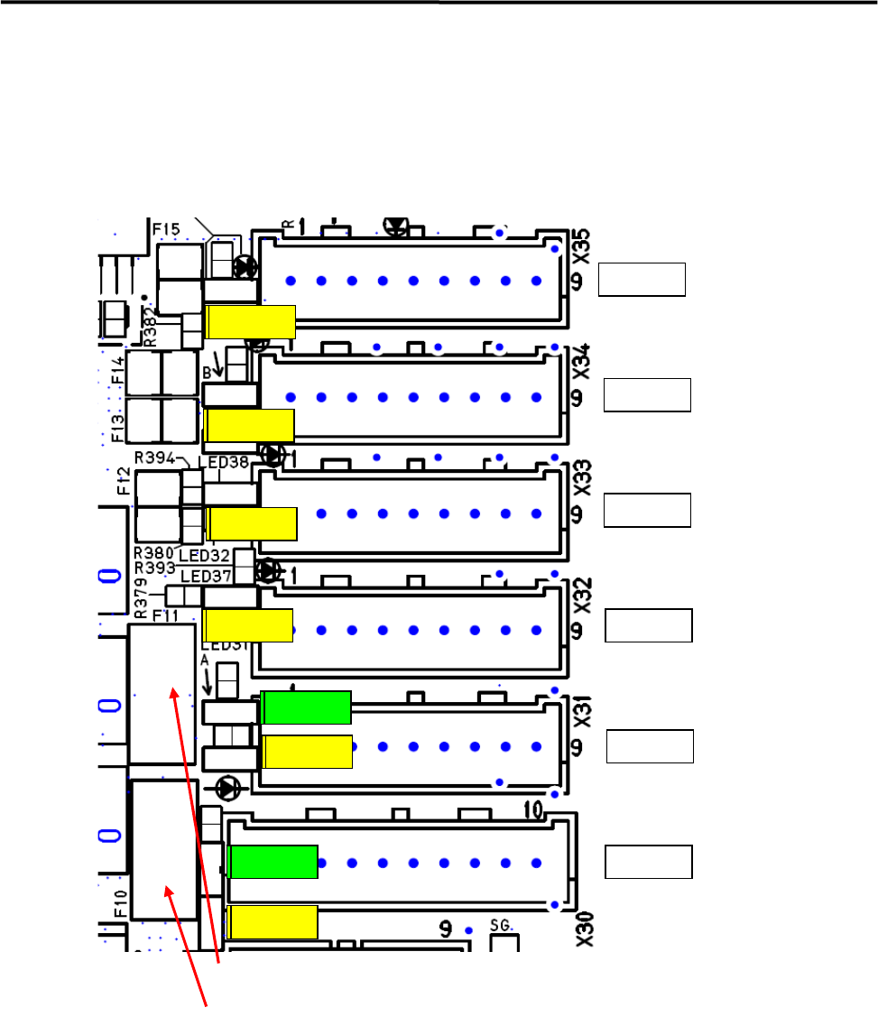
Serial I/O Operation Check LED
Fuses have been installed on Port 0 and Port 1 only, and the socket insertion type is used. .
When these fuses blow out, LED 35 & 36 for checking the power supply (green) will not be lit.
z LED 35 (Green) Port 0 is lit by supplying +5V to I/O board in communication with XiO board.
z Serial Communication has been established, and LED 29, 30, 31, 32, 33 and 34 (Yellow) are lit.
Port5
Port4
Port3
Port2
Port1
Port0
Fi30 or Ti11
Fi30 or Ti11
Fi30 or Ti11
Fi30 or Ti11
Hi11
Mi11
F10:Port0 +5VFuse (Socket Insert Type)
F11:Port1 +5V Fuse (Socket Insert Type)
LED29
LED35
LED30
LED36
LED31
LED32
LED33
LED34
LED29
LED35
LED30
LED36
LED31
LED32
LED33
LED34
4 Electrical Section
4-26
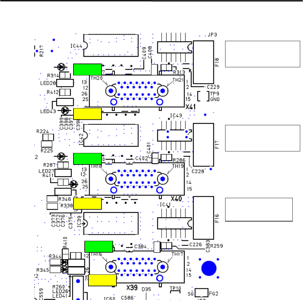
Vision Operation Check LED
F18:Fixed Camera(Rear)
+12V Fuse
(Socket Insert Type)
F17:Fixed Camera (Front)
+12V Fuse
(Socket Insert Type)
F16:Teach Camera
+12V Fuse
(Socket Insert Type)
LED28
LED43
LED27
LED26
LED42
LED41
z When +12 V is supplied to Cameras, then LED26 (Teach Camera), LED27 (Fixed Camera Front) ,
LED28 (Fixed Camera Rear) will be lit (Green).
z LED will be lit (Yellow) when receiving Image Data.
LED41; Teach Camera
LED42; Fixed Camera Front
LED43; Fixed Camera Rear
4 Electrical Section
4-27
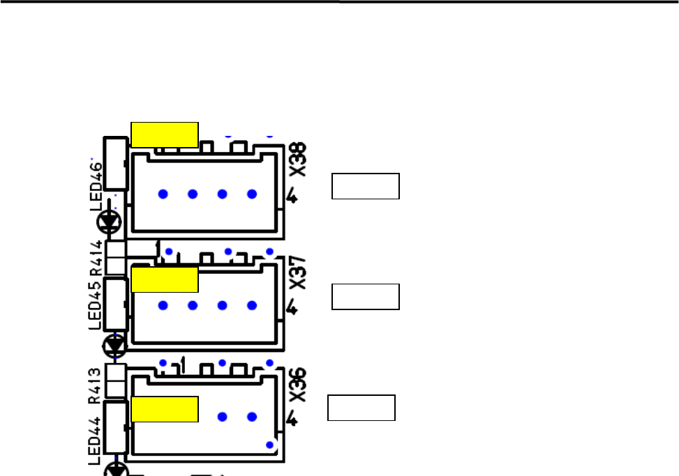
Motion Port Operation Check LED
z LED44 Port 0 (X, Y Axis) and 45 Port 1 (Z, T Axis) will be lit (Yellow) when receiving response data
from the servo amplifiers.
LED46
LED45
LED44
Port2
Port1
Port0
CTF
Z & T Axes
X&Y Axes