c900773.R02_EN.pdf - 第105页
4 Electrical Section 4-35 Cautions about overall electrical items Once rats enter facilities and production sites, they easily com e into machines and they m ay tear wirings and leave excrement that can cause serious dam…
4 Electrical Section
4-34
● LC2-M912A-00X PHOTO SENSOR WT4-2P112S34 (SICK)
z PCB arrival sensor
z Entrance buffer arrival sensor
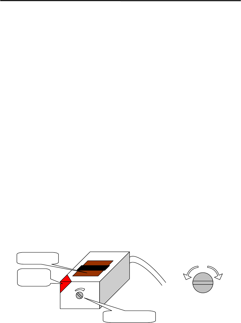
■ Adjusting Procedure
① Use a precision flathead screwdriver to turn the sensitivity thumb nut on an arrival sensor
counter-clockwise toward “min” all the way to its end. Place a PCB on the conveyor belt in the
direction as if it is place in an actual production operation. Slides the PCB along the conveyor belt and
move it to above a target sensor. Turn the sensor’s sensitivity thumb nut clockwise little by little
toward “max” until the reception indicator is lit.
NOTE: The sensitivity thumb nut can be revolved approximately five turns between the maximum and minimum
level positions. When the thumb nut is turned beyond the maximum or minimum level position, a ratchet
will be activated and the thumb nut idles with a chattering sound. The position at which such sound is heard
is the limit of the adjustable range of sensitivity.
② With the PCB placed on the conveyor belt, move it back and forth over the arrival sensor several times
by hand, and check to see that the receptive indicator turns ON and OFF in response to the detection
of PCB. (This refers to (A) thereafter.)
NOTE: The reception indicator displays three states of the sensor; ON = stable operation, OFF = no sensitivity,
Blink = unstable operation. When adjusting the thumb nut and checking sensor’s response to the PCB,
make sure that the indicator is completely lit and not blinking.
③ Turn the sensitivity thumb nut 1/4 turn (90 degrees) from position (A) clockwise toward “max”.
④ In order to verify the adjustment, go to [Manual] > [PCB Sensors ] and open the “PCB Sensors”
window. Check to see that the PCB arrival sensor/entrance buffer arrival sensor respond to the PCB
correctly. Also go to [Manual] > [Load Board] and check to see that the PCB is automatically
clamped properly.
NOTE: When the sensitivity is set excessively high, the arrival sensor may malfunction when the head passes over
it.
Reception
indicator
Emitter/Receiver
Sensitivity thumb nut
Lower
sensitivity
Higher
sensitivity
Sensitivity Adjustment
by thumb nut
4 Electrical Section
4-35
Cautions about overall electrical items
Once rats enter facilities and production sites, they easily come into machines and they may tear wirings
and leave excrement that can cause serious damage to machines.
When rats tear wirings, it may cause short circuits and it could lead to a serious problem to machines.
If rats leave excrement over printed circuit boards or torn and bared cables, it will be carbonized and may
catch fire.
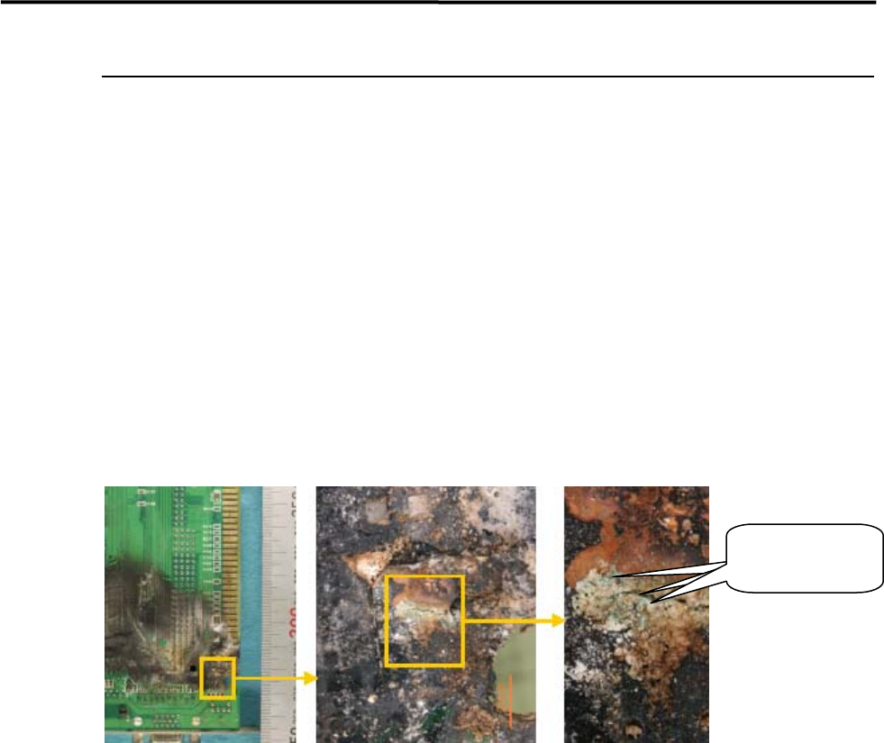
REFERENCE:
The following pictures are examples of a circuit board which caught fire.
In these pictures, the black-colored burn represents CuO (Copper II Oxide) and the red-colored burn
represents Cu2O (Copper I Oxide). Besides these, the bluish-green substance is considered Copper
Hydroxide. Based on these factors, it is presumed that the fire cause is infiltration of water.
COUNTERMEASURE:
1.Keep the facility and production line clean, neat and organized.
2.Lock up the room with no openings.
If once rats came in;
3.Sprinkle rat repellent.
4.Catch rats with adhesive sheets. (Emergency countermeasure)
5.Hire an rat exterminator.
To prevent damage caused by rats, it is important to keep rats-free environment.
When rats may have been already in the facility, exterminate them by using rat repellent or other ways as
mentioned above.
Bluish-green
substance
4 Electrical Section
4-36
Computer Virus Prevention and Treatment
Recently, virus infection on our machines has been increasingly reported and it is presumably due to USB
memory device with large storage capacity which is used for data backup and restore. It is primarily
important to prevent the machines from virus infection and, if the machines become infected, it is also
important to eliminate the virus immediately by using such tool as anti-virus software. This section
describes some examples of prevention against computer virus and treatment of the virus-infected
machines.
Computer Virus Prevention
Every machine is inspected by the latest virus checker and verified that they are not infected by virus before
shipment.
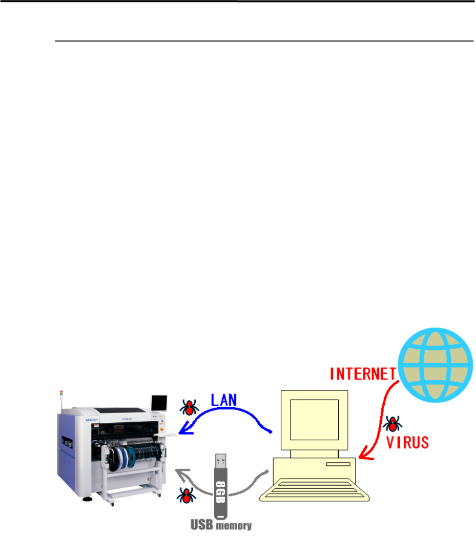
In most cases, route of virus infection is the internet. The machine has no capability to access the internet
and no possibility to be infected by virus directly through the internet. However, when any computer is
connected to the machine through LAN and it also connected to the internet, the computer may become
infected and it causes the secondary infection to the machine.
Besides this, data transfer between a virus-infected computer and the machine through USB memory
device is also one of the most possible causes.
Virus checker software cannot be installed in the machines. Followings are suggested for the prevention.
* Do not connect the machine to a computer through LAN which has an access to the internet.
* Install virus checker software into the computer which shares data with the machine.
* Frequently conduct virus scan by virus checker not only on the computer but also any other
storage device (USB memory device, etc.) which shares data with the machine.