c900773.R02_EN.pdf - 第36页
2 Periodical Checks 2-2 Daily Checks Visual Check Check the followings before turning on t he main swit ch and READY switch of the m ounter. NOTE: Power source and air supply m ust be in the ON state. ITEM DESCRIPTION Te…

2 Periodical Checks
2-1
2
Periodical Checks
2 Periodical Checks
2-2
Daily Checks
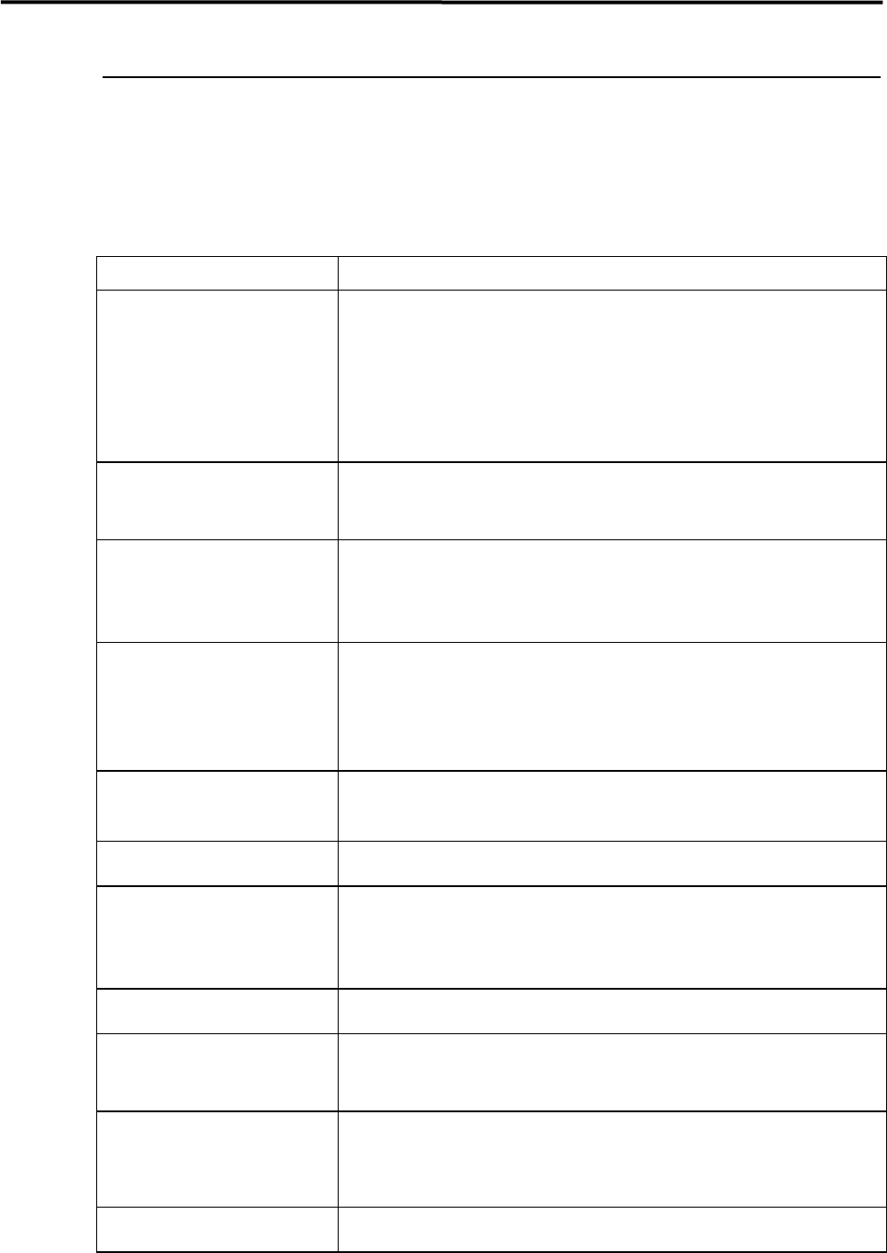
Visual Check
Check the followings before turning on the main switch and READY switch of the mounter.
NOTE: Power source and air supply must be in the ON state.
ITEM DESCRIPTION
Temperature and Humidity
Check the temperature and humidity.
Ambient Temperature:Accuracy assurance 23 +/-2 degrees centigrade
Operation assurance 5 to 35 degrees centigrade
(The average over a period of 24 hours does not exceed
30 degrees C.)
Relative Humidity:45 to 60 percent, non-condensing
Room Environment
If air is dusty, check air filters.
If mounter surface rusts as a result of corrosive gas, check vents, reflow ovens,
and board cleaners.
Air Supply
Make sure air pressure of regulator is 0.45 MPa
If drain cock contains water, drain it. (Adjusting temperature of dry air may be
required.)
If drain contains oil, investigate the cause.
Reject Tray (Front & Rear)
Make sure of the setting direction of the reject tray.
Make sure that the ends of the reject tray and the tape guide (on which station No.
sticker is placed) meet.
Make sure that the reject tray sits properly and is not lifted by electronic
components.
Conveyor
Make sure conveyor width of all the peripherals are the same.
Make sure no obstacles are on conveyor.
Head Moving Range
Make sure no obstacles are in head moving range, e.g. on the adjust plate.
Fixed Camera
Make sure no obstacles are on half mirror, lens, or lens filter of fixed camera, and
check those parts for dirt. Clean if dirty.
)
”Camera” in 3 Mechanical Section.
ANC
Make sure no obstacles are around ANC tower.
Nozzle
Clean nozzles if dirty. Replace if deformed.
)
”Nozzle” in 3 Mechanical Section.
Feeder Bank
Clean front and rear feeder banks.
Make sure tape feeders are set on bank securely. If not, it may cause head
collision.
Input/Output Terminal Assembly
Check connections of connectors and air hoses.
2 Periodical Checks
2-3
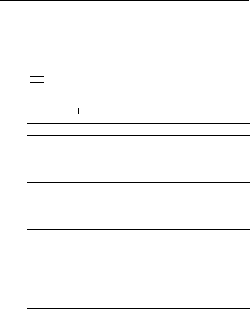
Manual Check
Check the followings after turning on the main and READY switch of the mounter.
If the mounter conditions or movements are not normal, an error message will appear on the LCD. Refer to
error messages in the reference manual.
ITEM DESCRIPTION
Main switch
Check if display of MENU screen is normal after starting system.
Ready switch
Check if indicator lights when switch is pressed.
If not, turn off system and turn it on again.
EMERGENCY STOP
switch
Check function by pushing and releasing it.
Origin
Check if heads return to origin properly.
Jog
Check if display of head coordinates is proper.
Make sure there is no unusual noise when head is traveling in each axis (X,Y,Z
and Theta). .
Suction
Check if negative pressures of all heads are within range.
Conveyor
Check conveyor movement by transferring PCB.
Stopper
Check stopper movement.
Clamp
Check clamp movement.
Main Clamp
Check main clamp movement
ANC
Check ANC movement.
Head
Check head movement.
Signal I/O
Check capability of sensors in Signal I/O screen.
Refer to reference manual.
Air Pressure
Check head/nozzle choke and solenoid valve failure.
)
3 Mechanical Section.
X-Y Table
Make sure X and Y axes and ball screws do not give unusual noise when traveling
head.
Check that proper amount of grease is provided.