c900773.R02_EN.pdf - 第131页
6 . Additional Function 15 Placement of Dispense Head Follow the instructions below and place the dispense head. Insert the fluid shortage det ection magnet ASSY to the plunger inside the sy ringe. Place the syringe hold…
6.Additional Function
14
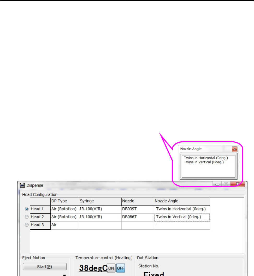
3. Manual > Dispense > Head Information
3-1. Right-click on a “DP Type” cell and select “Air (Rotation)”.
3-2. Right-click on a “Syringe” cell and select a desired code.
Right-click on a “Nozzle” cell and select a desired code.
Right-click on a “Nozzle Angle” cell and select either “Twins in Horizontal (0deg)” or
“Twins in Vertical (0deg)”.
Select the nozzle angle as if the sum of pickup data’s θaxis value and dispense data’s θoffset value
becomes “0” degree.
Since compensation is applied according to the orientation of nozzle, the orientation of nozzle does
not need to be specified when the nozzle is attached to the dispense head.
6.Additional Function
15
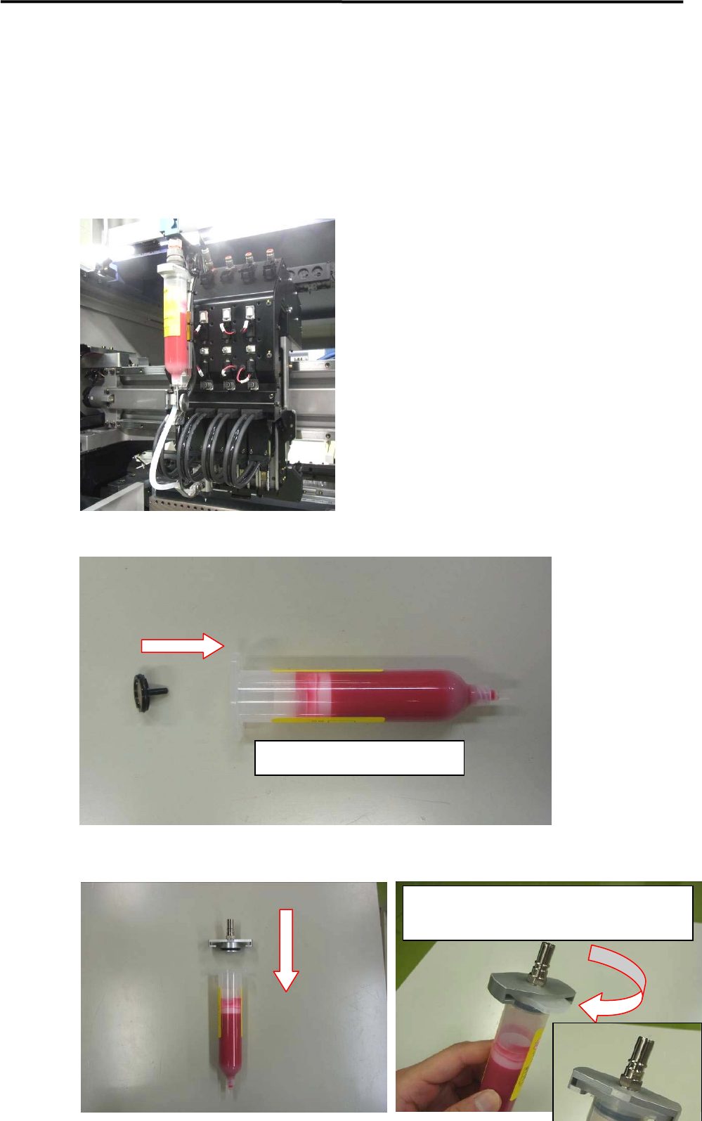
Placement of Dispense Head
Follow the instructions below and place the dispense head.
Insert the fluid shortage detection magnet ASSY to the plunger inside the syringe.
Place the syringe holder.
Insert the magnet into the plunger
Rotate the syringe holder until its collar meets the
color of the syringe.
6.Additional Function
16
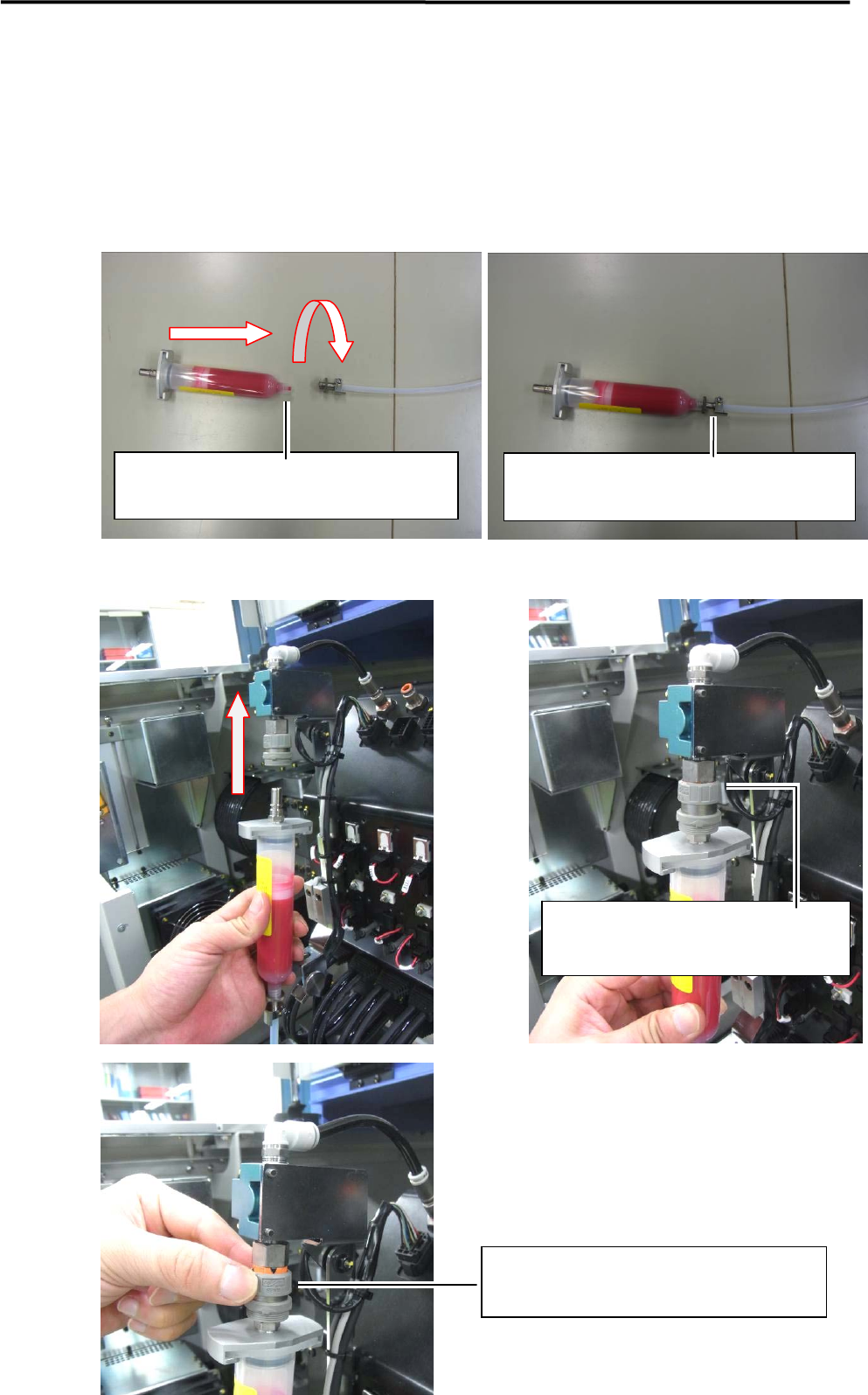
Connect the syringe to the tube joint.
Connect the syringe to the valve.
Twist the syringe clockwise and screw it in the
tube joint.
Push the syringe upward until it makes a
clicking sound.
Turn the secure knob clockwise and lock it.
Do not twist off the screw thread of the syringe by
the tube joint.