c900773.R02_EN.pdf - 第50页
3 Mechanical Section 3-10 O-ring When the O-ring in side the nozzle deteriorates an d develops cracks, air leakag e will occur. This will reduce the maximum air pressure (negative pressure), and will cause pro blems with…
3 Mechanical Section
3-9
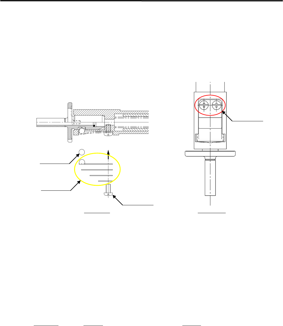
Entry of dust and dirt between a roller and leaf springs that hold the nozzle may cause unsmooth
performance of the roller and leaf springs and nozzle-dropping. Make a periodic check of the nozzle escape.
When any *abnormal conditions are seen, clean the nozzle holder. (*The nozzle stays up and does not go
back to its initial position, or the nozzle drops easily etc.)
NOTE: Please handle the roller and leaf spring inside the nozzle holder carefully, since they are small and likely to
be lost easily. It is recommended that spare parts should be kept handy before removal.
roller
leaf spring
pan-head screw
pan-head screw
Side View
Front View
ACTION:
① Unscrew the two screws with a Phillips screwdriver to take off the roller and leaf springs.
② Remove dust and dirt from the roller and leaf springs, as well as around the area where the roller
touches on the nozzle holder.
Check to make sure that there is no flaw on them. (Replace the part if any flaw is found.)
③ Apply the proper amount of Silicone Grease to the roller and the area where it touches on the nozzle
holder .
Put the roller and leaf springs back in reverse order of removal and secure them with screws.
● Inspection Interval
When unusual conditions are seen by an inspection., or once/twice a month.
Part Name
Part No. Remark
SCREW,BIND.HEAD LC1-M71GN-30X Pan-head screw
PIN,PARALLEL LC6-M71AY-00X Parallel pin
LEAF,SPRING 1 LC6-M714R-00X Leaf Spring 1
LEAF,SPRING 2 LC6-M714S-00X Leaf Spring 2
LEAF,SPRING 3 LC6-M714T-00X Leaf Spring 3
LEAF,SPRING 4 LC6-M714U-00X Leaf Spring 4
NOTE: Life span of leaf springs is approximately five hundred thousand nozzle changes. They should be replaced
periodically.
3 Mechanical Section
3-10
O-ring
When the O-ring inside the nozzle deteriorates and develops cracks, air leakage will occur. This will
reduce the maximum air pressure (negative pressure), and will cause problems with suction operation.
When the reduction in the maximum air pressure is found and the cause seems to be in the nozzle, replace
the O-ring inside the nozzle.
ACTION:
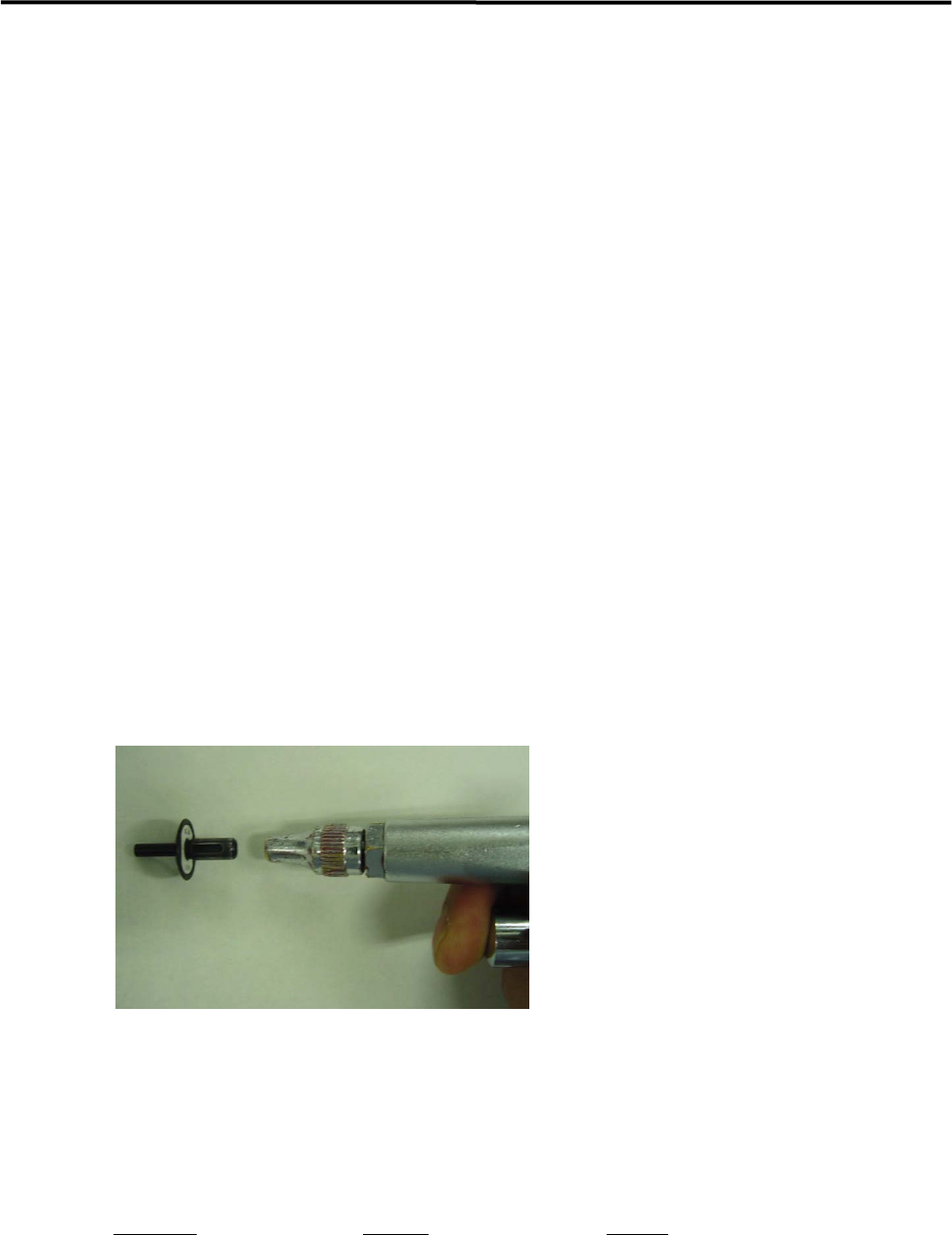
① Pull out the O-ring from the nozzle and clean inside the nozzle with an air blower.
② Insert a new O-ring into rear end of the nozzle.
③ Push the O-ring against the bottom inside the nozzle.
④ After the new O-ring has been set in place, attach the nozzle to the head and check for nozzle
clogging.
)
Checking the nozzle for clogging
NOTE: Do not apply silicon grease or the like to the O-ring since it may cause nozzle clogging.
■ Nozzle Filter
The nozzle filter keeps dust and dirt from entering inside of the nozzle. It also prevents the escape action
malfunction caused by the dust. Periodic cleaning of the nozzle filter must be performed.
ACTION:
① Clean the nozzle by blowing the air with an air blower from its rear end.
NOTE: Normally, cleaning with the air blow may be sufficient, but remove the O-ring and the filter and clean them
when the dirt is firmly attached to them.
NOTE: Nozzles with filter:
P005, P006, P013, P018, P019, P020 and Custom-made nozzles.
Dust and dirt are easily entered into a nozzle hole of large-diameter nozzles. (1.0mm or larger)
Part Name
Part No. Remark
O RING LC1-M77A5-90X
FILTER, NOZZELE 15 LC6-M771Y-00X
REMOVER,O-RING LC1-M861R-01X O-ring removal jig
PIN(O RING) LC1-M8911-10X For inserting O-ring
3 Mechanical Section
3-11
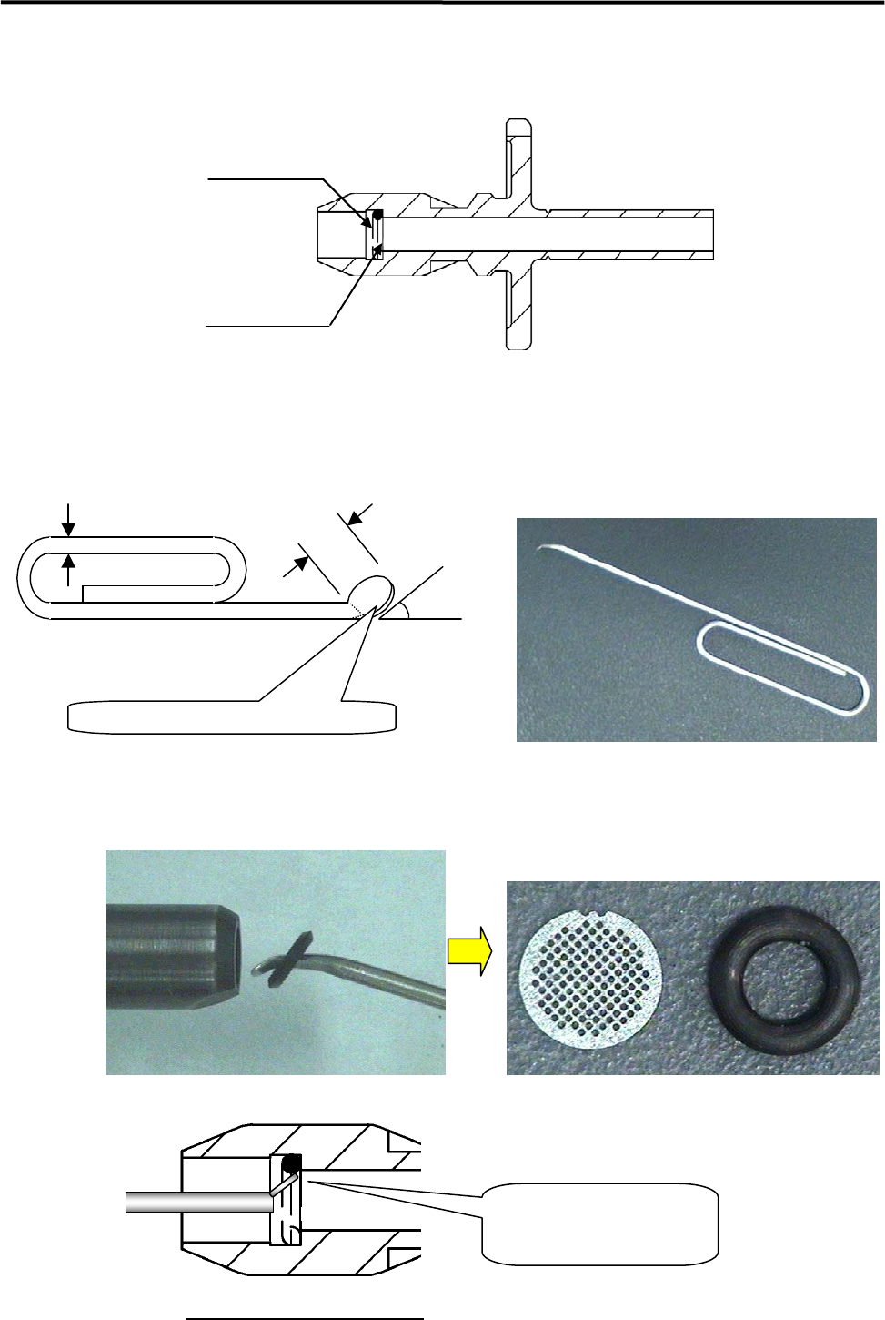
■ Removing O-ring and Nozzle Filter
NOTE: The filter is fixed by the O-ring. It has no right-side up.
O-ring
Filter
ACTION:
① Insert an O-ring removal jig like illustrations below into the nozzle from its rear end.
Jig: Modify a commercially available clip.
Dia.1mm
3mm
30 to 45 degrees
Flatten the pin edge by pliers.
(
t=0.3mm
)
② Insert the flattened pin-edge of the jig between the O-ring and the nozzle filter, and pull out the O-ring
from the nozzle (Carefully pull out the jig and do not drop the O-ring.).
Magnified view of O-ring part
■ Attaching O-ring and Nozzle Filter
Insert the flattened pin-edge
between the O-ring and the filter.