c900773.R02_EN.pdf - 第119页
6 . Additional Function 3 Fix the dispense holder. Place the dispense head. Fix the dispense head. End Tighten the flange with a wrench. WRENCH, 14-5NW LE6-M5W22-100 Adjust the rotation angl e of the dispense head and in…
6.Additional Function
2
Dispense Head
Placement of Dispense Head
Mount head needs to be changed to dispense head.
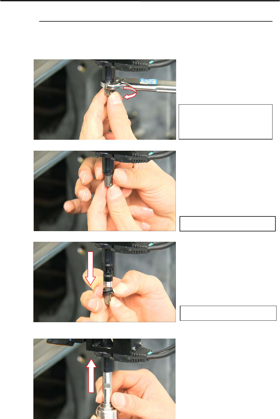
Removal of Nozzle Holder
Remove the flange.
Remove the nozzle holder.
Place the dispense holder.
Loosen the flange with a wrench.
WRENCH, 12-1NM
LE6-M5W22-000
Loosen the flange.
Pull the nozzle holder downwards.
6.Additional Function
3
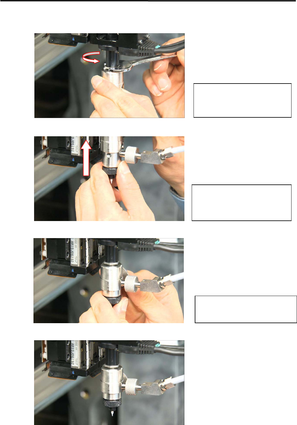
Fix the dispense holder.
Place the dispense head.
Fix the dispense head.
End
Tighten the flange with a wrench.
WRENCH, 14-5NW
LE6-M5W22-100
Adjust the rotation angle of the
dispense head and insert it to the
dispense holder.
Tighten the secure knob and fix the
dispense head.
6.Additional Function
4
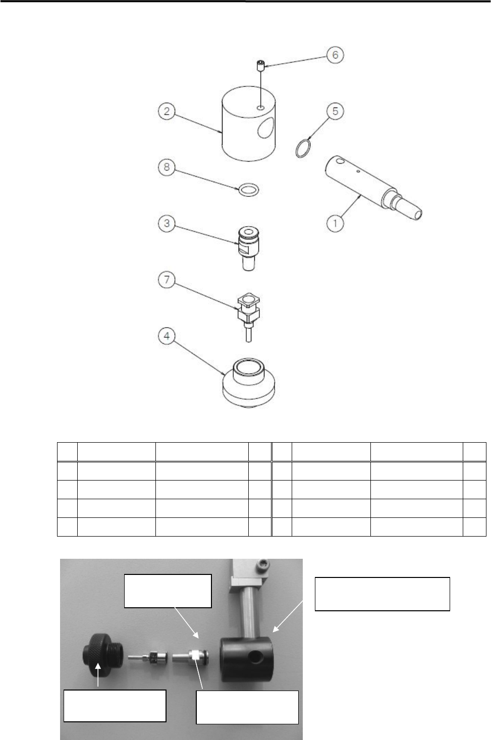
Assembly of Standard Dispense Head
PART LIST
No. PART NO. PART NAME Q
’
TY No. PART NO. PART NAME Q
’
TY
1 LE6-M5F5N-00x PIPE, FITTING 1 5 LE6-M5FBV-00x O-RING 1
2 LE6-M5F65-00x BRACKET NOZZLE 1 6 LE6-M5FF7-10x SET, SCREW 1
3 LE6-M5F69-00x ADAPTER 1 7 LG7-M740S-xxx SINGLE NOZZLE SEL. 2
4 LE6-M5F6A-00x LOCK, ADAPTER 1 8 90200-02J050 O-RING 1
Assembly of the standard head requires the following parts.
BRACKET NOZZLE
LE6-M5F65-00x
ADAPTER
LE6-M5F69-00x
LOCK ADAPTER
LE6-M5F6A-00x
O-RING
90200-02J050