c900773.R02_EN.pdf - 第43页
3 Mechanical Section 3-3 ■ Air Passage To maintain the designed accuracy and com ponent-placem ent rate of the m achine, clean the air passage between the air filter assy. and nozzle ho lder periodically. ACTION: Carry o…
3 Mechanical Section
3-2
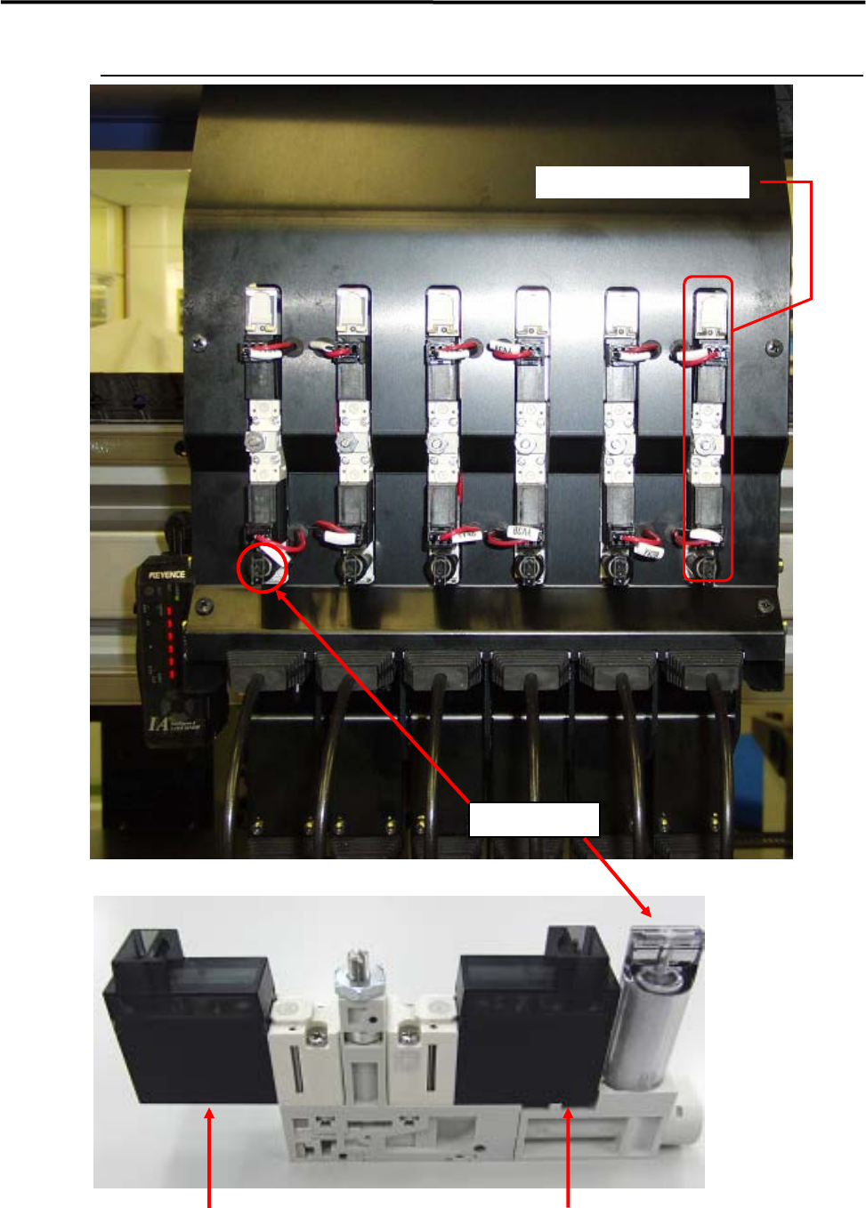
Head Manifold Section
Solenoid Valve (6 pieces)
Air Filter Cap
Supply Valve
LE6-M71A2-B0X
Breaking Valve
LE6-M71A2-C0X

3 Mechanical Section
3-3
■ Air Passage
To maintain the designed accuracy and component-placement rate of the machine, clean the air passage
between the air filter assy. and nozzle holder periodically.
ACTION: Carry out vacuum break operation for a few seconds with the nozzle removed.
● Cleaning Interval
Approx. once a week
■ Air Filter
ACTION: Remove a filter element from the air filter assy. and remove dust and dirt collected inside the assy. by air
blowing. Then, check the white air element for dirt. When it is excessively dirty, replace it with a new one.
If an O-ring attached on the filter cap gets dirty, wash it with water or diluted neutral detergent, and dry it
well. If there are cracks on the o-ring, replace it with a new one since the cracks may cause air leakage.
● Inspection Interval
Once a week, and when a choking error occurs
Part Name
Part No. Remark
FILTER LE6-M71A2-E0X Filter Element
■ Vacuum Generator
ACTION: Check the silencer element visually. When it is excessively dirty, replace it with a new one. Also measure
the maximum air pressure to inspect whether the vacuum generator can generate a proper vacuum.)
Inspection for Head/Nozzle Clogging and Solenoid Valve
● Inspection Interval
Once a week

3 Mechanical Section
3-4
Inspection for Head/Nozzle Clogging and Solenoid Valve
Breakdown
The following inspection must be carried out approximately once a week.
■ Inspection of Solenoid Valve
The switching valve of the solenoid valve may catch foreign matter causing air leakage. Air leakage will
turn the suction ON even if it is turned OFF.
As a result, the suction cannot be turned OFF after a component is mounted, and components may be
brought back instead of being mounted on a PCB.
● Inspecting by Selecting [Manual] – [Air Pressure]
①Checking the maximum air pressure
Turn ON the suction and press the head tip with fingers to check the air pressure. The air pressure is
satisfactory when it is “600” or higher.
②Checking the head for clogging
With no nozzles placed in the head, turn ON the suction to check the air pressure. Typical air pressure is
approx. “40”. An error occurs when the air pressure is “120” or higher during vacuum check performed at
nozzle replacement.
③Checking the nozzle for clogging
With nozzles placed in the head, turn ON the suction to check the air pressure. “Choke Threshold” has
been assigned to each nozzle and the air pressure must be below it. If it is not, the nozzle will be considered
to be clogged and an error occurs.
④Checking the solenoid valve for switching failure
Turn OFF the suction and check for change in the air pressure.
- Press the head/nozzle tip with fingers and check for change in the air pressure.
- Turn ON and OFF the suction a few times and check for change in the air pressure.
If the air pressure changes even though the suction is OFF, air is probably leaking from the suction solenoid
valve.
NOTE: Do not disassemble the solenoid valve. Manufacturer’s guarantee will be ineffective once the solenoid
valve is disassembled.
Part Name
Part No. Remark
VALVE LE6-M71A2-B0X Supply Valve
VALVE LE6-M71A2-C0X Breaking Valve
NOTE: For official and more precise inspection, use a digital vacuum meter and check accuracy of the displayed air
pressure value.
Part Name
Part No. Remark
MANOMETER ASSY. LC1-M89A5-00X Vacuum Gauge Set