c900773.R02_EN.pdf - 第21页
1 Installation 1-7 ③ When the mounter is instal led stand alone, turn the adjust feet so that the PCB transfer height is the same as the conveyor hei ght (900 ± 20mm (see Note)) of the reference equipm ent. When the moun…
1 Installation
1-6
ACTION:
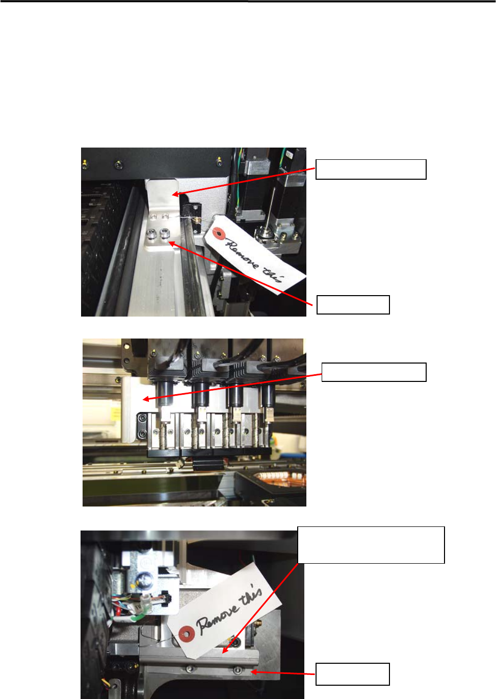
① Locate the mounter to the specified place.
② Remove the followings: the bolt that locks the head in the X-axis beam and the metal fitting that
prevent X-axis beam movement to the Y direction. After removed the bolts and fittings, confirm that
the head can move to the X direction and the X-axis beam can move to the Y direction manually.
Note; Please keep the bolts and metal fittings, they will be necessary if moving the machine.
X Axis Fixing Bracket
Fixing Screw
Head Fixing Bracket
Y Axis Fixing Bracket
(two brackets at both sides)
Fixing Screws
1 Installation
1-7
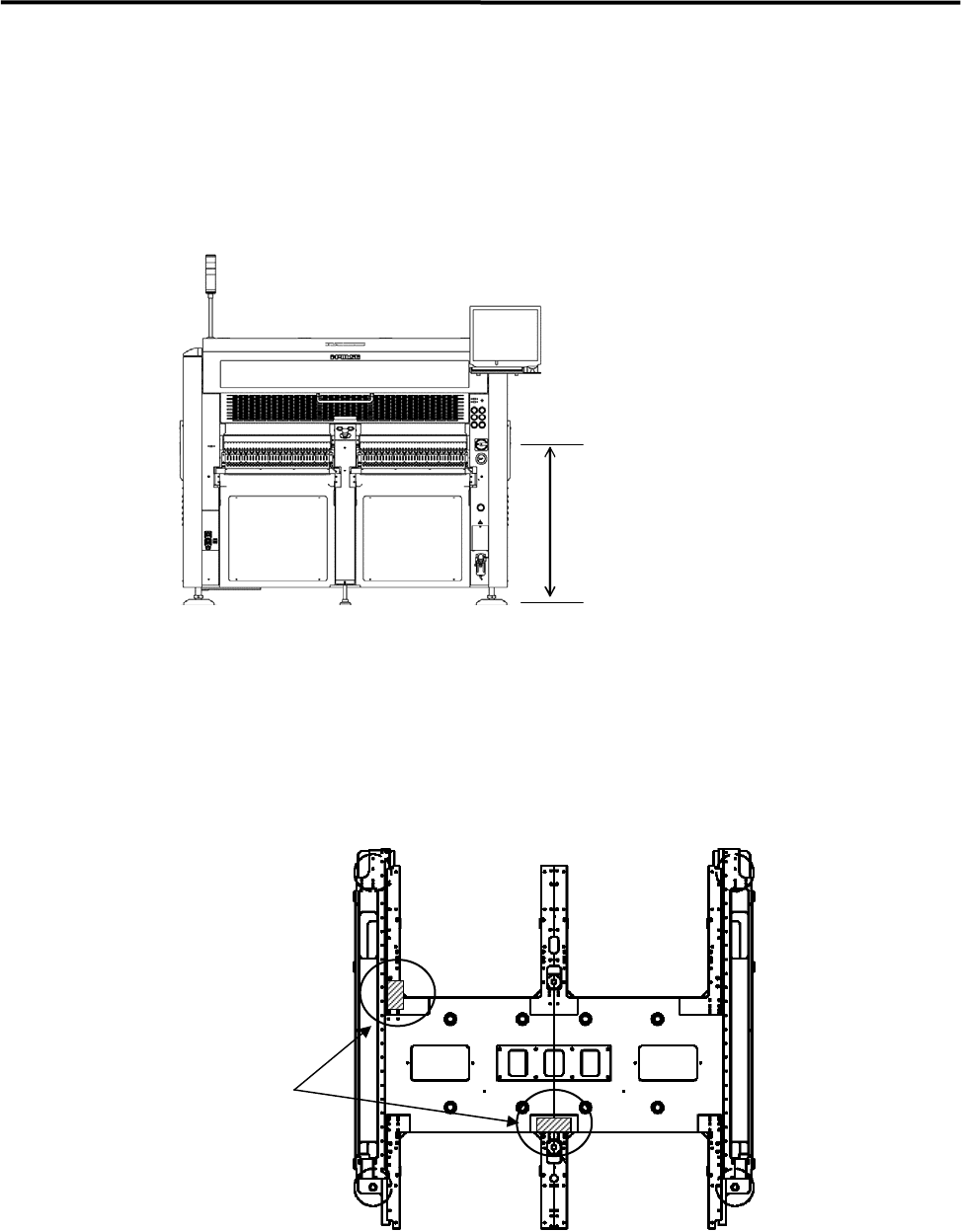
③ When the mounter is installed stand alone, turn the adjust feet so that the PCB transfer height is the
same as the conveyor height (900±20mm (see Note)) of the reference equipment.
When the mounter is connected to the Pre-process on production line, adjust the PCB transfer height
to the conveyor rail height of the Pre-process.
)
Production Line
In the case of SMEMA interface spec, the height must be 950±20mm.
900±20mm
または、
950±20mm(SMEMA 規格)
NOTE: The height must be 890 to 920mm in the case of CFB wagon spec.
NOTE: The adjust feet must be turned using a M30 single-head wrench (nominal: 46mm).
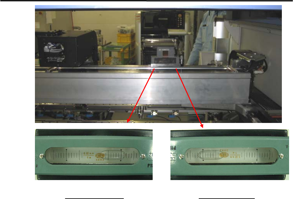
④ Place a leveler on the base of the mounter. Set the position to the conveyor of the Pre-process finely
until the mounter is leveled.
) Supplementary Explanation for Installation
⑤ After the mounter is positioned, make sure that a board runs smoothly between upstream and
downstream conveyor.
⑥ Place a leveler on the X-axis beam and make a fine adjustment so that the difference in indicator when
the X-axis beam moves forward and backward will be within 1 division. ( To prevent a X-axis beam
distortion. )
Ll
Levers
1 Installation
1-8
Viewed from the front
Viewed from the rear
⑦ Lock the adjust foot nut lastly.
NOTE: The adjust foot nuts must be locked with a closed wrench (nominal: 46mm) or a single-head wrench.
⑧ Connect the power cable and ground line independently of other machines which may be a noise
source, such as a compressor, welding machine.
⑨ Connect an intake-side air coupler 65SN or 85SN (Nitto Kohki) or equivalent to the air regulator
coupler located on the rear of the mounter. After the coupler is connected, make sure that the air
regulator’s reading is 0.5MPa(5.1 ㎏ f/c ㎡).