DECAN_S1_Administrator′s_Guide(Eng_Ver1.5)_Print.pdf - 第105页
4-23 Tools Shortcut Menu Ref. Once the value of the teaching of the deleted Z column can not be undone. <Off set Check> group <He ad> combo box Selects the head to measure the board flatness. <PrevDe…
4-22
Next Generation, Multi-Functional Placer DECAN S1 Administrator’s Guide
<Position> group
<Light> button
Outer
Adjusts the outer lighting for the Down Camera of the selected Gantry.
Inner
Adjusts the inner lighting for the Down Camera of the selected Gantry.
<Move> button
Move the fiducial camera of the selected gantry.
<Get> button
Applys the coordinate value of the current position as the selected fiducial
mark position.
<PrevMove> button
The fiducial camera moves from the current position to the previous position.
<NextMove> button
The fiducial camera moves from the current position to the next position.
<InitialXY> group
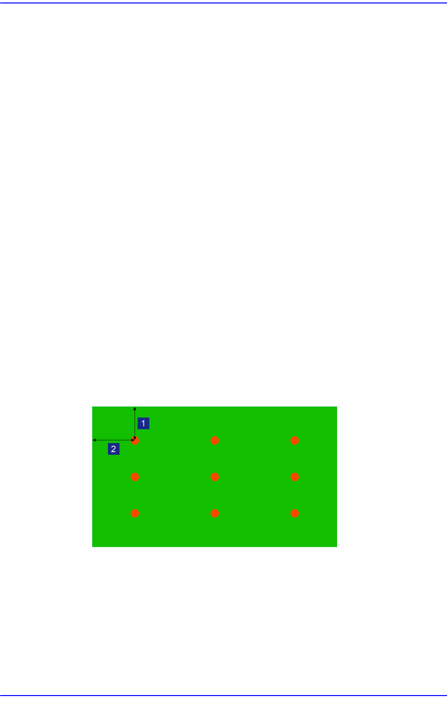
<MarginX> editbox
Refers to the margin in the X direction of the board.
<MarginY> editbox
Refers to the margin in the Y direction of the board.
1: MatginY
2: MarginX
<Clear> button
Deletes the teaching values of the Z-column in the <Spread> group.
4-23
Tools Shortcut Menu
Ref. Once the value of the teaching of the deleted Z column can not be
undone.
<Offset Check> group
<Head> combo box
Selects the head to measure the board flatness.
<PrevDetect / NextDetect> button
<PrevDetect> button: Measures the previous coordinate value of the
coordinate currently selected in the <Spread> group.
<NextDetect> button: Measures the next coordinate value of the coordinate
currently selected in the <Spread> group.
Ref. The <PrevDetect / NextDetect> button is enabled when the
<Manual> check box is selected.
<Manual> check box
Teach the Z values at the X and Y coordinates manually using the
<PrevDetect / NextDetect> button.
<Detect Z> button
Teach the Z value for the X and Y coordinates of the cell currently selected in
the <Spread> area.
<Automatic> check box
After selecting the Z column to be measured in the <Z> combo box, pressing
the <Detect Z> button will measure the Z column automatically.
4-24
Next Generation, Multi-Functional Placer DECAN S1 Administrator’s Guide
4.7.2. Head Tab dialog box
Performs setup of camera lighting or check of head operation by manually recognizing
parts with vision system.
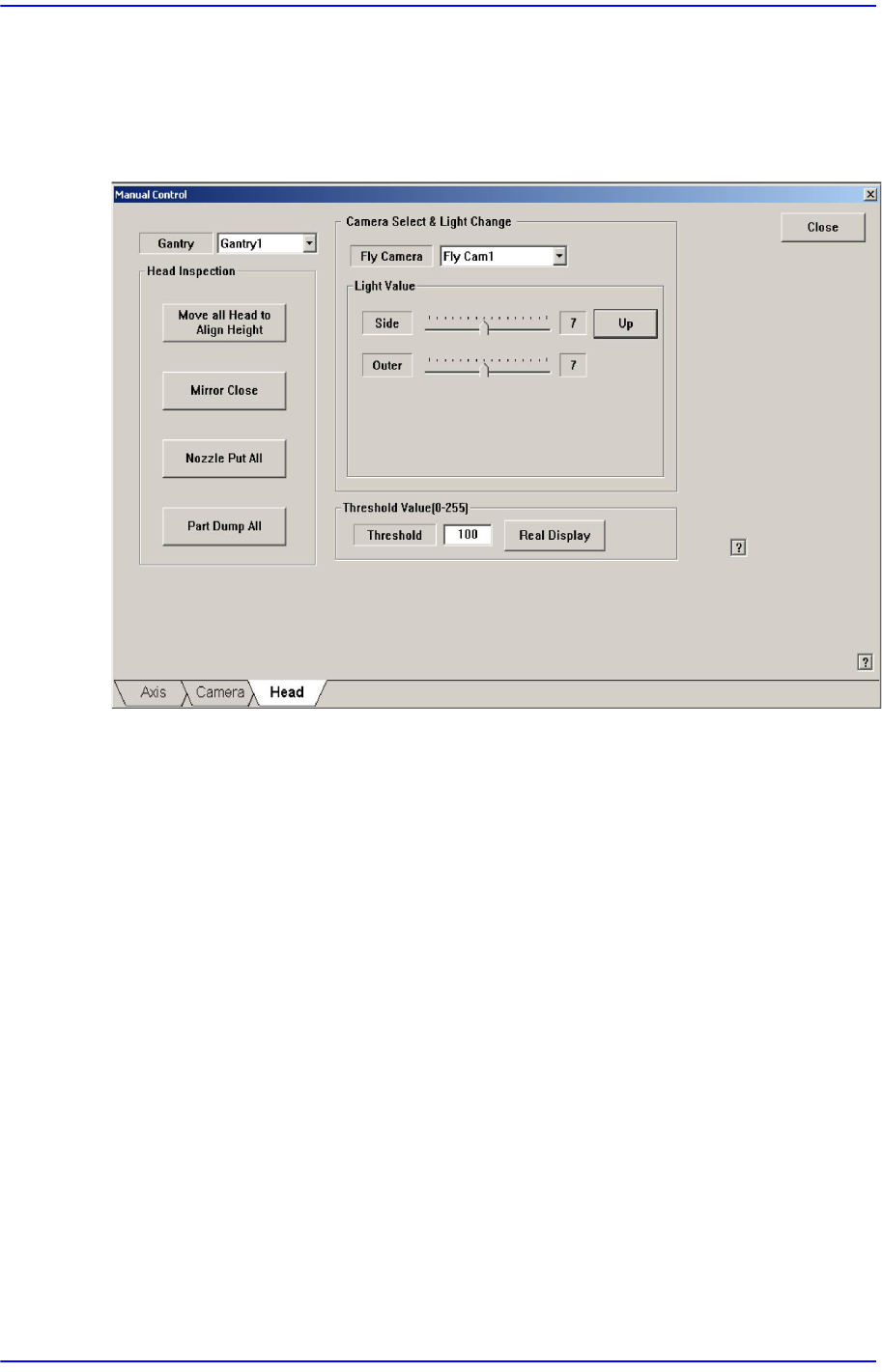
Figure4.8 “Manual Control – Head” dialog box
<Gantry> combo box
Select the gantry to which the head to be tested belongs.
<Head Inspection> group
<Move all head to align height> button
Put the nozzle tip of the head at the align height for parts recognition.
<Mirror Open/Close> button
Open or close the mirror for parts recognition.
<Nozzle Put All> button
Return all nozzles placed at the head to the ANC.
<Part Dump All> button
Dump all the picked up parts at the dump box.
<Camera Select & Light Change> group
Set the illumination value of the fly camera. Select the fly camera whose illumination
is to be adjusted and adjust the slide bar in the <Light Value> group to adjust the
brightness.