DECAN_S1_Administrator′s_Guide(Eng_Ver1.5)_Print.pdf - 第231页
7-67 Part Registration Selecting the <Use Polyg on> check box will disable the <Lead Parameter & Group> button and <MFOV T ype> combo box. This enables the <Auto T each> button. At this time, …
7-66
Next Generation, Multi-Functional Placer DECAN S1 Administrator’s Guide
<Body Y Max> edit box
Set the maximum size of component body in Y direction.
<Body Y Min> edit box
Set the minimum size of component body in Y direction.
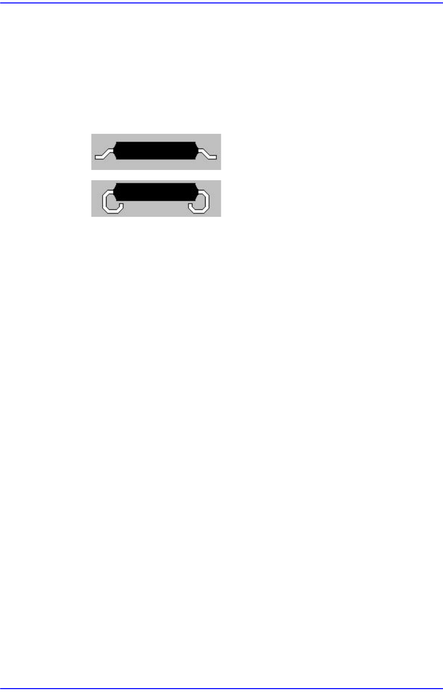
<Lead Type> combo box
Select the lead type. Available lead types are as follows.
Gull-Wing: Leads protrude outward as QFP.
J-Lead: Leads roll inward as PLCC.
<Algorithm> combo box
Select the algorithm to recognize the component. Available algorithms are as
follows.
Black Body
Used in case only lead is displayed brightly on the screen since the color of the
component body is black.
All Body
Used in case lead and body are displayed brightly on the screen since the color
of the component body is bright.
Odd with No Lead
Used for odd shaped parts for which recognition accuracy is not important. Its
recognition algorithm is similar to that of the trimmer.
Odd with Lead
Used for odd shaped parts with leads.
<Lead Parameter & Group> button
Set the lead parameter and lead group.
Please refer to“7.1.1 common Align Data”.
<Option> group
Set the align option data.For other setups, please refer to“7.1.1 common Align Data”.
<Use Polygon> check box
In the case of the part whose recognition precision is not significantly important,
this is used to recognize the part automatically using the Auto Teach function.
Adjust the Threshold and Ex Parameter to suit the characteristics of the
corresponding part so that it can be recognized automatically.
7-67
Part Registration
Selecting the <Use Polygon> check box will disable the <Lead Parameter &
Group> button and <MFOV Type> combo box. This enables the <Auto Teach>
button.
At this time, in the <Body X> and <Body Y> edit box of the <Size> group, set the
size of the area in which the polygon is to be searched.
The area in which the polygon is to be searched can be set up by adding the value
entered in the <Area Margin> edit box to the value set by the <Size> group.
Clicking the <Ex Param> button will display the following dialog box. The value
from 0 up to 10 can be set in the <Body Sub Sample> edit box of the <Extra
Parameter> tab dialog box.
The value set here determines the fineness when creating the outline of the part in
the SM Vision window.
If the image displayed in the SM Vision window has a lot of noise or is unclear, set
its value to the default value of ‘0’.
If the image is clear and therefore the outline of the part can be distinguished
plainly, the part outline can be created with fine detail.
However, if the outline becomes rough due to an over-increase in the value, the
part may not be recognized correctly.
1- Finest Outline
10 –Roughest Outline
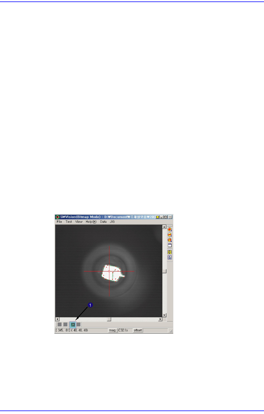
1: Polygon Toolbar
Polygon Toolbar button
When recognizing a part, the part recognition center can be designated by
dragging the crosshair with the mouse.
At this time, the center of the camera becomes the part recognition center by
default. Match the recognition center (origin point) of the polygon part to be
7-68
Next Generation, Multi-Functional Placer DECAN S1 Administrator’s Guide
recognized with the crosshair center. Then the crosshair center becomes the
center of the area in which the polygon part is to be searched.
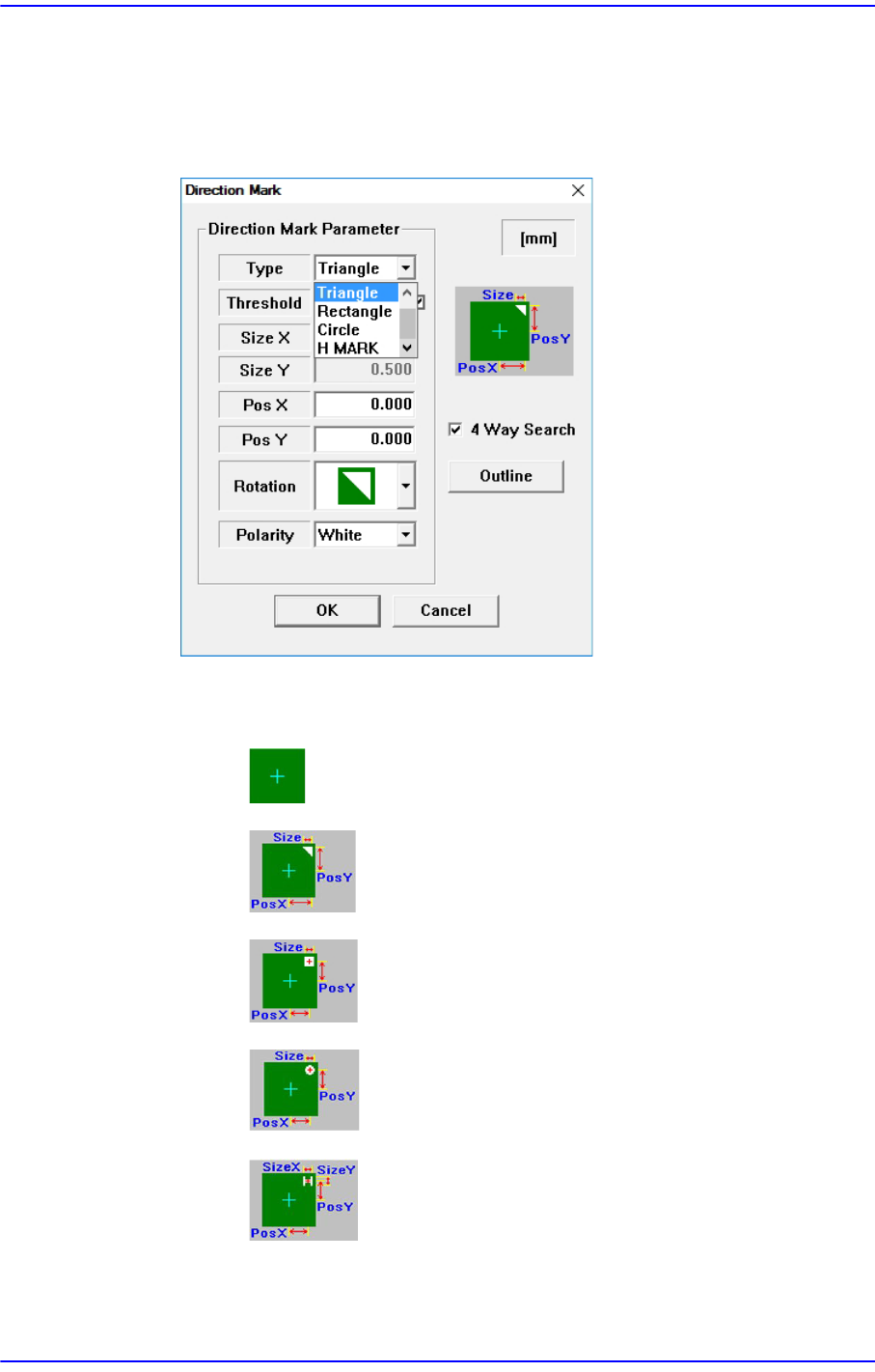
<Direction Mark> button
Sets the part placement direction.
<Direction Mark Parameter> group
<Type> combo box
None: There is no Direction Mark.
Triangle: Selected when the direction mark is a triangle.
Rectangle: Selected when the direction mark is a rectangle.
Circle: Selected when the direction mark is a circle.
H MARK: Selected when the direction mark is “H” mark.
<Threshold> edit box
The image viewed through the SM Vision window is composed of each