DECAN_S1_Administrator′s_Guide(Eng_Ver1.5)_Print.pdf - 第280页
8-22 Next Generation, Multi-Functional Plac er DECAN S1 Administrator’s Guide 8.1.3. Tray Unit Set various data for tray feed ers. When “Tray Unit” is selec ted, the initial screen looks as follows. Figure8.8 “Tray Un it…
8-21
Feeder Setup
<Display> button
Displays the shape of the feeder that is installed on the feeder base graphically.
8-22
Next Generation, Multi-Functional Placer DECAN S1 Administrator’s Guide
8.1.3. Tray Unit
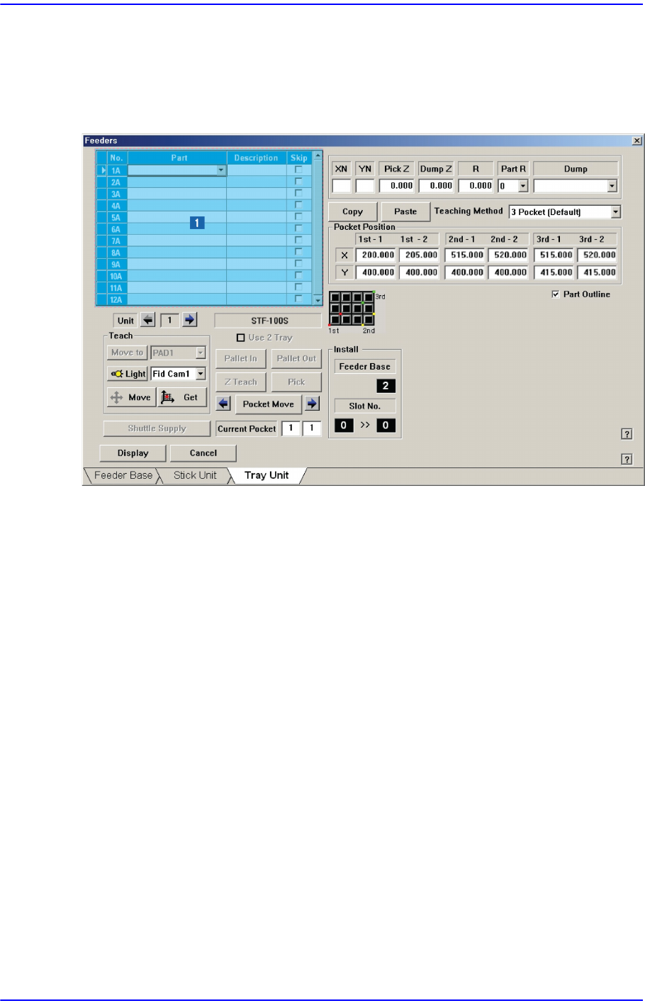
Set various data for tray feeders. When “Tray Unit” is selected, the initial screen looks as
follows.
Figure8.8 “Tray Unit” dialog box
1: <Grid> group
<Grid> group
Create and edit data according to the type of the corresponding tray.
<No> column
Refers to the serial number of the tray unit. Basically, “Single” has 10 trays. Each
means one tray.
<Part> column
Select the part to install on the corresponding tray. When the <Part> column is
clicked on, a combo box appears, and among the components registered in <1.2
Part>, a list of components to be supplied to “Tray” are displayed.
Next is the screen that shows component selection in the combo box of <Part>
column.
8-23
Feeder Setup
<Skip> column
Determines whether to pick up the part fed from the corresponding pallet.
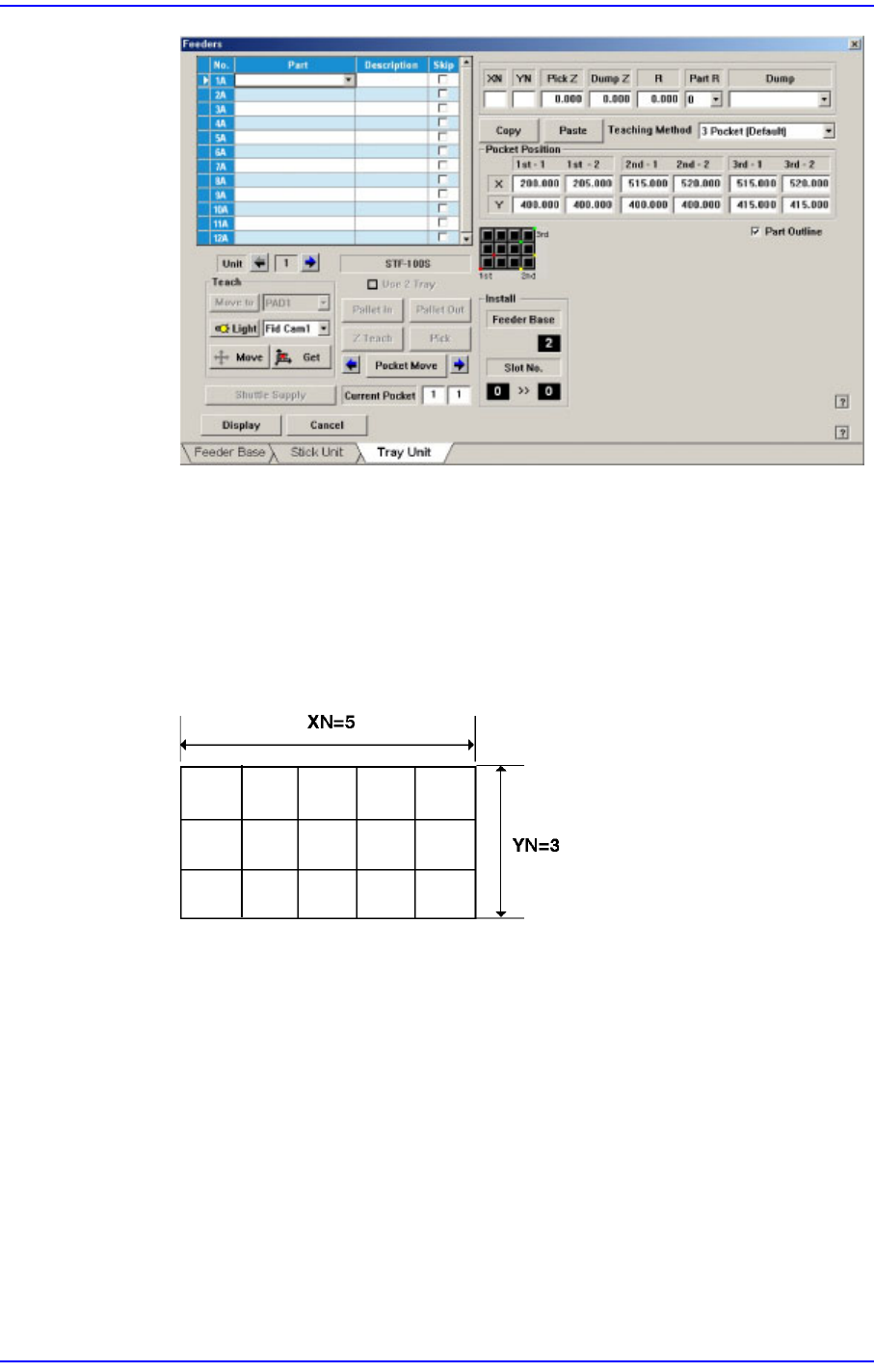
<XN> edit box
Sets the number of pockets of the selected pallet in the X direction.
<YN> edit box
Sets the number of pockets of the selected pallet in the Y direction.
<PickZ> column
Sets the Z axis height when picking up the part fed from the corresponding palle.
<DumpZ> column
Sets the Z axis height when dumping the part if part pickup has failed. At this
time, it must be set to ‘Return to Tray’ in the <Dump> column.
<R> column
Sets the R axis coordinate (head rotation angle) when picking up the part fed from
the corresponding pallet.
<PartR> column
Sets the pickup angle of the part fed from the corresponding pallet.