DECAN_S1_Administrator′s_Guide(Eng_Ver1.5)_Print.pdf - 第480页
15-14 Next Generation, Multi-Functional Plac er DECAN S1 Administrator’s Guide 15.3. Peripherals [F6] Performs setup for the dump box, tray feeder , flu x device and LCR Checker . 15.3.1. <Dump Box> tap dialog Setu…
15-13
System Setup
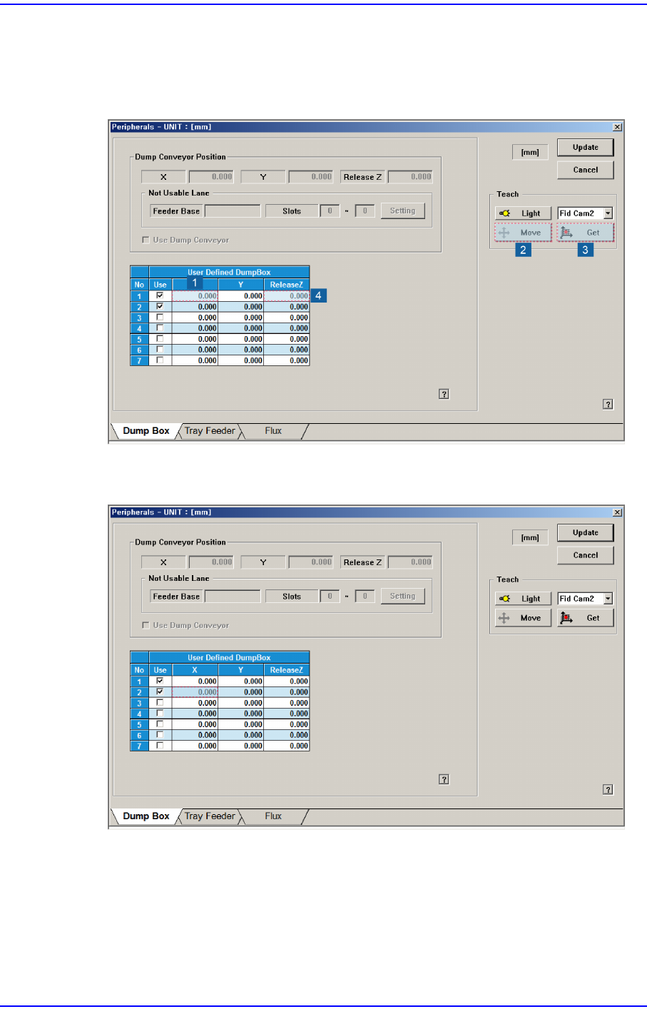
2. After selecting No. 1 in the following figure, click the <Move> button to move the Fid
Cam1 to the position of the Front Air Shower. Then match the jig fiducial mark with
the camera center and click the <Get> button. Finally, input -10 in the <ReleaseZ>
column.
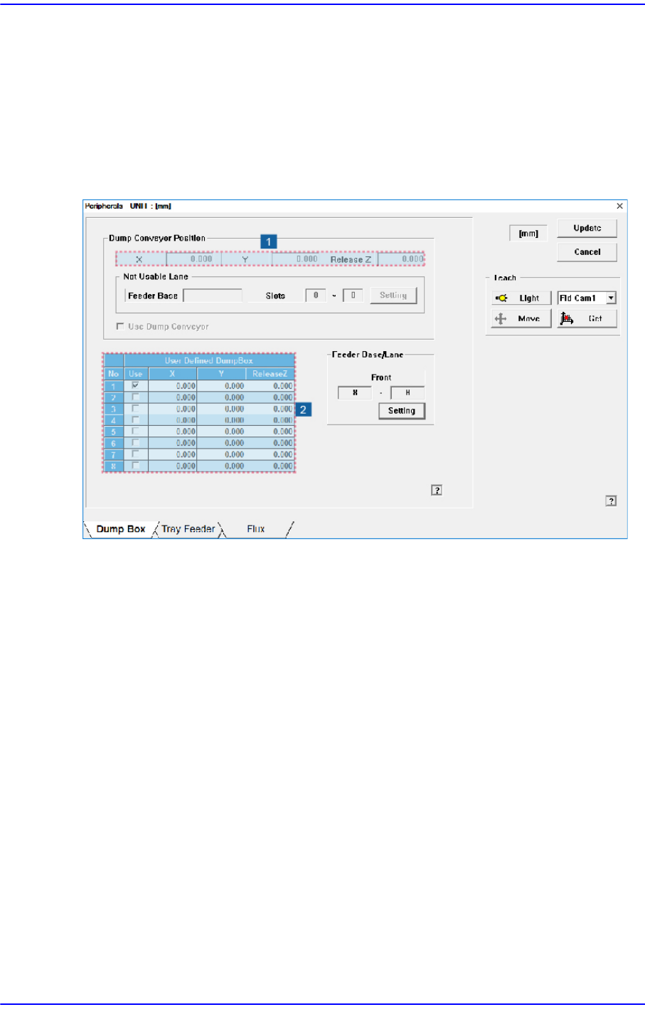
3. For the No. 2 row checked in the following figure, teach the air shower position in the
same manner as the above No.2 step.
15-14
Next Generation, Multi-Functional Placer DECAN S1 Administrator’s Guide
15.3. Peripherals [F6]
Performs setup for the dump box, tray feeder, flux device and LCR Checker.
15.3.1. <Dump Box> tap dialog
Setup items related with the ‘Dump Conveyor’ and ‘Dump Box’ defined by the user.
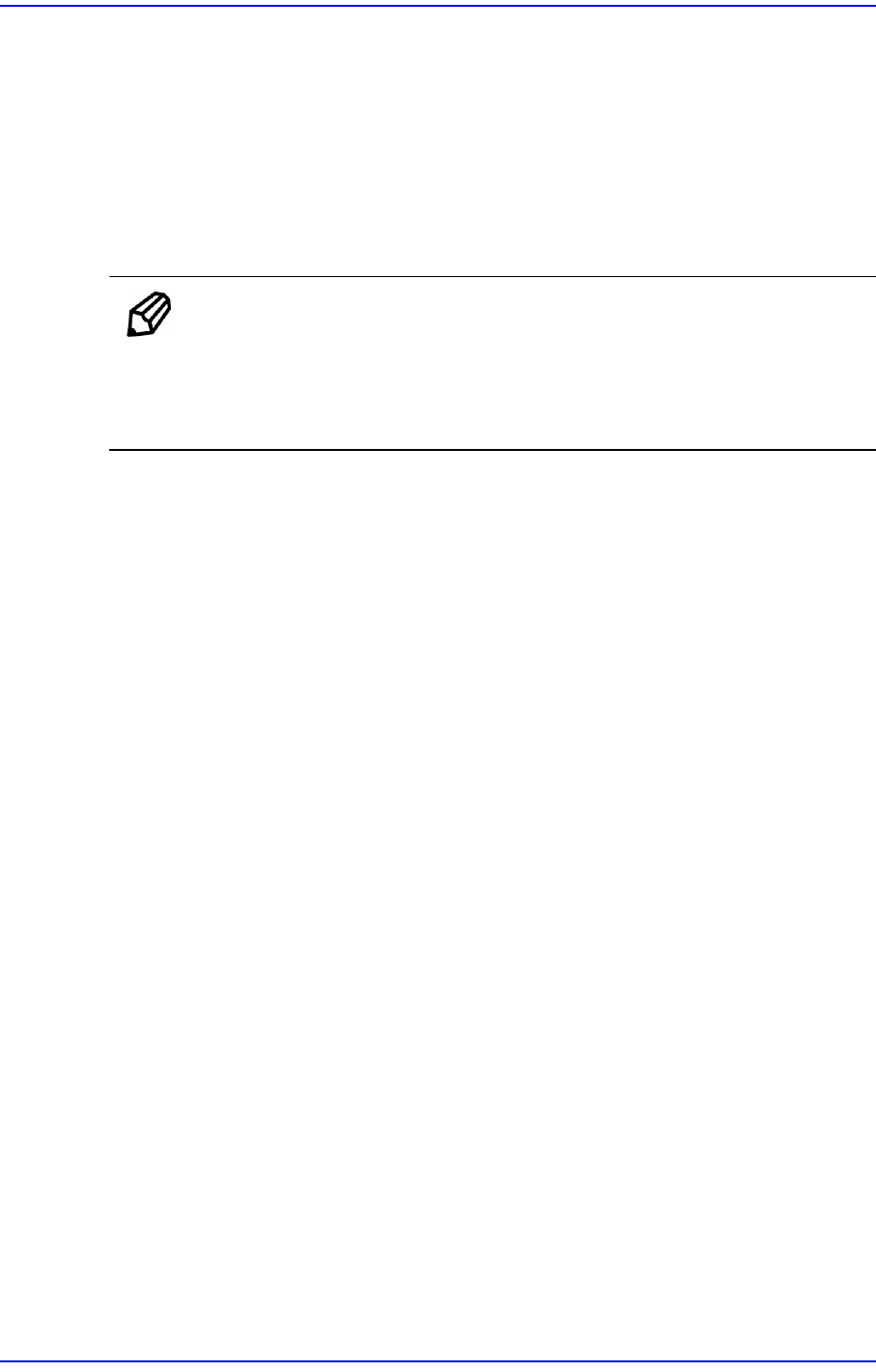
Figure15.7 “Dump Box” tap dialog
1: <Position> group
2: <User Defined Dump box> group
<Dump Conveyor Position> group
Inputs the items to be set related to the dump conveyor. From the equipment which it
sees it is a function which it does not support.
<Position> group
X, Y: Enter the part dumping position on the dump conveyor by teaching the X
and Y coordinates.
Release Z: Enter the Z axis height when dumping the part.
<Not Usable Lane> group
From the equipment which it sees it is a function which it does not support.
<Setting> button
Clicked to set the feeder group that cannot be used due to the installation of
the dump conveyor.
<Use Dump Conveyor> check box
Determines whether to use the dump conveyor. D This check box must be selected
15-15
System Setup
to set the dump conveyor related items.
<User Defined Dump box> group
Setup the data related with the ‘User Dump Box’ installed by the user. The maximum
number of ‘User Dump Box’ able to be installed by the user is 8.
‘User Dump Box’ is utilized for dumping parts in the ‘User Dump’ position when
dumped parts are expensive, or require classification, or parts error has occurred in a
box installed in the equipment by the user.
Memo “System default Dump Box” is assigned as the default box when
‘Dump’ item of the feeder supplying the corresponding part in the
feeder dialog box is not assigned after setting up the ‘User Dump
Box’.
Method of setting up the ‘User Dump Box’ is as follows;
1.Select <Use> check box and move the head to the position where the ‘User Dump
Box’ is installed using the ‘Teaching Box’.
2.Select ‘Fid Cam’ in the <Teach> area, and fit the center of the ‘User Dump Box’ to
the center of cross lines of the ‘Fiducial Camera’ seen on the SMVision monitor.
3.Select the corresponding cell in the <User Defined Dump box> group with the
mouse, and Input the value of the present coordinates by clicking on the <Get>
button.
4.Click on the <Update> button to reflect the changed value.
After updating, select ‘User Dump’ of the feeder supplying parts using ‘User
Dump’ in the feeder dialog box.
<User defined Dump Box - No> column
Indicates the number of ‘User Dump Box’.
< User defined Dump Box - Use> column
Setup whether to use the corresponding ‘User Dump Box’ or not.
< User defined Dump Box - X> column
Setup the X position of the corresponding ‘User Dump Box’.
< User defined Dump Box - Y> column
Setup the Y position of the corresponding ‘User Dump Box’.
< User defined Dump Box –Release Z> column
Setup the height of the head Z-axis while dumping in the corresponding ‘User
Dump Box’.