DECAN_S1_Administrator′s_Guide(Eng_Ver1.5)_Print.pdf - 第184页
7-20 Next Generation, Multi-Functional Plac er DECAN S1 Administrator’s Guide That is, the speed is controlled in 2 step s for the Z axis . For example, if cracks occur frequently in the part. The overall speed of the Z …

7-19
Part Registration
<Z Place Down> combo box
Select driving speed of the Z-axis driving motor while the head is descending
to place parts. If the speed is inappropriate according to the part, it will cause a
crack to be created in the part or have other influence on the part.
The “Soft Touch” function can be used together, if needed.
<Z Place Up> combo box
Select driving speed of the Z-axis driving motor while the head is ascending to
place parts. If the speed is inappropriate according to the part, it may have bad
influence on the placement accuracy.
The “Soft Touch” function can be used together, if needed.
<Z Align Speed> combo box
Sets the speed at which the Z axis moves up and down for the Fix Camera to
recognize a part or the speed at which the Fly Camera moves to the Z axis
movement height after recognizing the part.
This speed is applied separately from the Z axis speed that was set in the <Speed>
group and <Soft Touch> combo box and it is applied as the Z axis movement
speed only for part recognition.
For existing machines, it was moved referring to the Z Place Down/Up movement
speed for the above two movements.
Therefore, when the Z Place Down/Up movement speed is set slow for precision,
the movement to the Z axis recognition or the movement from the fly camera to
the Z axis movement height after recognition was inevitably slow.
To overcome such disadvantage, the function designating the speed of the above
two movements was added.
In the case of micro parts to which a pickup error can easily occur according to the
Z axis movement speed, change the value here and perform a recognition test.
Then set the value when recognition is successful and register the part.
<Insp Only Zero> check box
In the case of a specific part, the difference in the recognition ratio often occurs
according to the direction in which the part is picked up to the nozzle when
recognizing the part.
At this time, if this function is selected after the corresponding part is registered
based on the direction for better recognition ratio, the part is recognized always at
the registered angle when recognizing the corresponding part. This function is
applied mainly to TR or IC parts.
<Soft Touch> combo box
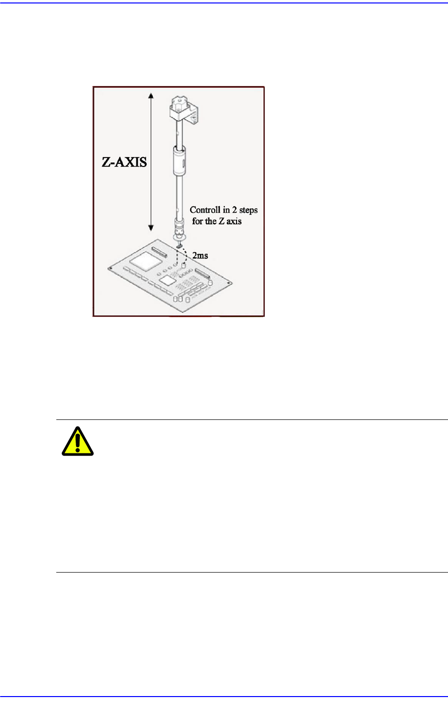
This can be applied for the part pickup and placement. It allows the speed of the Z
axis to become 4 (slow) at 2mm height from the PCB upper surface when the head
moves down regardless of the speed set in the <Speed> group.
7-20
Next Generation, Multi-Functional Placer DECAN S1 Administrator’s Guide
That is, the speed is controlled in 2 steps for the Z axis. For example, if cracks
occur frequently in the part. The overall speed of the Z axis may be reduced.
However, in this case, overall efficiency decreases.
At this time, the work can be done efficiently using this function.
Not Use: Set this function so that it is not used.
Pick: Set this function so that it is used only for pickup.
Mount: Set this function so that it is used only for placement.
Pick&Mount: Set this function so that it is used only for pickup and
placement.
Caution In case of shock sensitive components like CSP or μBGA,
the z-axis related speed parameters must be set according
to the component manufacturer’s specification or standards.
And use the nozzle suitable to component manufacturer’s
specification or standards.
If necessary, please contact our Business Department or
the local agent for the nozzle suitable to component
manufacturer’s specification or standards.
7-21
Part Registration
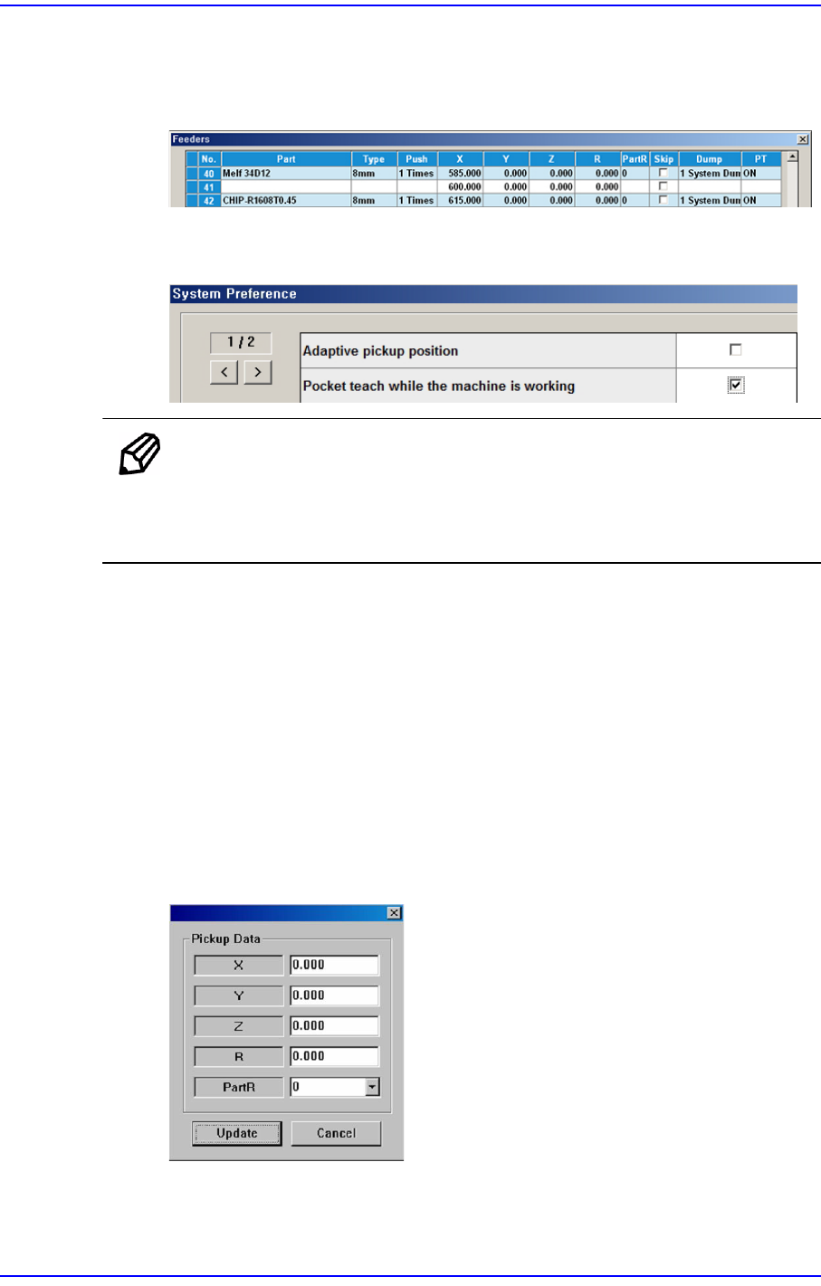
<Enable Pocket Teach> check box
If this check box is selected, the Pocket Teach function of the feeding device that
feeds the corresponding part is automatically set up in the 'Feeders' dialog box.
In order to allow the Pocket Teach to be actually applied, the Pocket Teach option
of the Preference submenu of the System Setup menu must be set up.
Memo For parts fed by an 8mm tape feeder, it is recommended that this
function be applied.
Basically, the black splicing tape must be used.
<Pick Up Data> button
Sets the offset of the pickup point coordinate when picking up a specific part. For
some specific parts, the pickup point set by default may differ from the actual
pickup point.
(Example: It is not possible to pick the part at the center)
At this time, after teaching the actual pickup point for the corresponding part, save
the pickup point offset here and register the corresponding part as a part to be
placed and then the offset is automatically applied to the pickup point so that it is
not necessary to teach the pickup point again.
In order to use this function, input the coordinates taught in the edit box.
X/Y
It is recommended to use X/Y without setting the offset.