DECAN_S1_Administrator′s_Guide(Eng_Ver1.5)_Print.pdf - 第248页
7-84 Next Generation, Multi-Functional Plac er DECAN S1 Administrator’s Guide Figure7.29 “Ball Gap of BGA component-when there is a selected area” dialog box <Create All > button Creates all balls. <Remove A…
7-83
Part Registration
<GAP> button
If there are any missing balls in the ball arrangement, sets the empty balls. It is
activated only when the <Grid Type> is “Regular”.
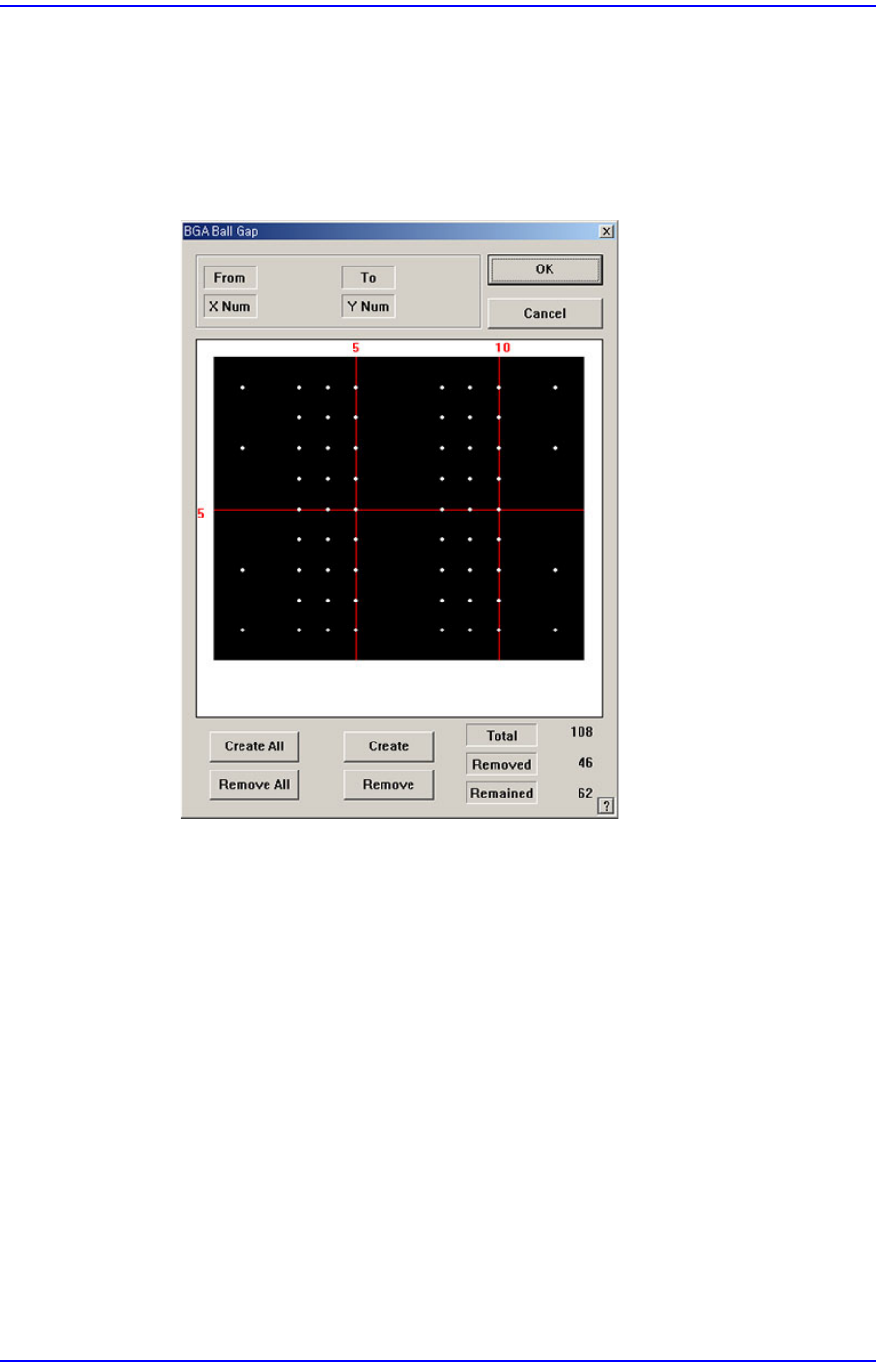
When this button is clicked on, the following dialog box is displayed.
Figure7.28 “BGA Ball Gap” ”dialog box
The grid displays the current ball status. The white dot indicates the ball. To
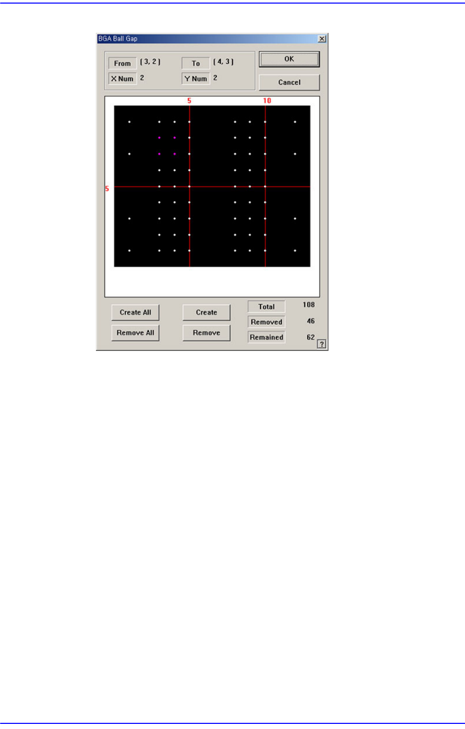
remove balls in a certain area, the area should be specified first. The area to select
can be set by pressing the left button of the mouse, drag it to the desired area and
release it. The balls in the selected area change color. The following screen shows
a case where 4 balls in total, from the ball at (3,2) to the ball at (4,3), 2 balls in X
direction and 2 balls in Y direction, are selected.
7-84
Next Generation, Multi-Functional Placer DECAN S1 Administrator’s Guide
Figure7.29 “Ball Gap of BGA component-when there is a selected area” dialog box
<Create All> button
Creates all balls.
<Remove All> button
Removes all balls.
<Create> button
Creates balls in the selected area.
<Remove> button
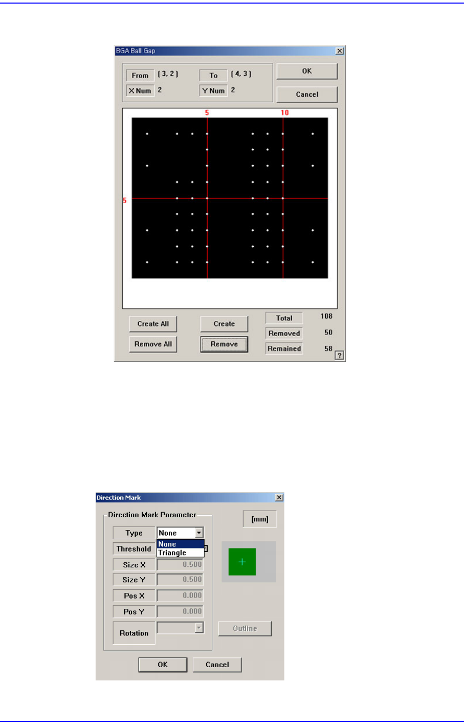
Removes the balls in the selected area.
When the balls in the selected area are removed, the screen looks as follows.
7-85
Part Registration
Figure7.30 “Ball Gap of BGA components-when balls in the selected area are
removed” dialog box.
<OK> button
Saves the set ball gap status and closes the dialog box.
<Cancel> button
Closes the dialog box without saving the set ball gap status.
<Direction Mark> button
Set the direction of the BGA.
For details of other than this, refer to “7.1.1 common Align Data” for more