DECAN_S1_Administrator′s_Guide(Eng_Ver1.5)_Print.pdf - 第484页
15-18 Next Generation, Multi-Functional Plac er DECAN S1 Administrator’s Guide Note: The nonstop function is not used. Master/Slave: One rack is used as master and another rack is used as slave. Master/Master: One …
15-17
System Setup
15.3.2. <Tray Feeder> Tab dialog
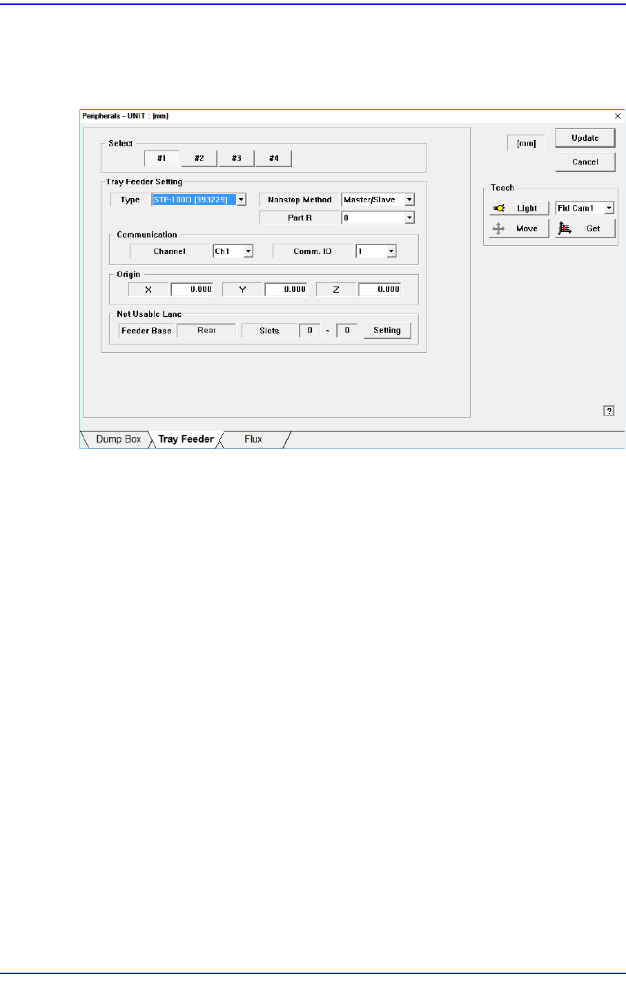
Sets the tray feeder related data. Selecting this button will display following dialog box.
Figure15.8 “Accessory” dialog box “Tray Feeder” Tab dialog
<Select> option button
Selects the tray feeder unit. Available tray feeder units are No. 1 to No.4 tray feeder
units.
That is, a total of 4 tray feeders can be installed. (Maximum 2 trays can be installed for
the type of trays that can communicate with the equipment.)
<Tray Feeder Setting> group
Selects the type of the set tray feeder unit. Available type is as follows.
<Type> combo box
Selects the type of the set tray feeder unit. Available type is as follows:
NONE: Means that no tray is installed.
Single Tray[39321]: Refers to the tray installed on the feeder base.
FW-20NS [393227]: Non-stop tray feeder with 20 stages.
STF-100N [393228]: Non-stop tray feeder with 20 stages.
STF-100D [393229]: Non-stop tray feeder with 24 stages.
STF-100S [393230]: Non-stop side tray feeder with 20 stages.
STF-100E [393231]: Tray feeder with 20 stages.
<Nonstop Method> combo box
Determines whether to use the non-stop function.

15-18
Next Generation, Multi-Functional Placer DECAN S1 Administrator’s Guide
Note: The nonstop function is not used.
Master/Slave: One rack is used as master and another rack is used as slave.
Master/Master: One rack is used until the parts are exhausted, and then another
rack is used.
<Part R> combo box
Set the placement angle for the component supplied from the tray feeder.
<Communication> group
Set the data related to RS-232C communication.
<Channel> combo box
Select the RS-232C communication channel. 2 channels are available for the
machine. Perform setup so that it may not be duplicated.
<Comm. ID> combo box
Select the communication ID. The used ID is 1 –3. Since only ID 1 is
supported, set the ID to ID 1.
<Origin> group
Setup origin of the selected ‘Tray Feeder Unit’. This origin is the offset value from
the origin of the equipment.
<Not Usable Lane> group
Sets the feeder base unit and slot occupied by the corresponding tray when using the
selected tray feeder unit.
<Feeder Base> combo box
Selects the feeder base. The selectable feeder base is front (Front Feeder Base or
Rear Feeder Base).
<Lane> edit box
Sets the slot the feeder base.
<Update> button
Transmits the change data to the equipment and closes the dialog box.
<Cancel> button
Ignores the change data and closes the dialog box.
15-19
System Setup
15.3.3. <Flux> Tab Screen
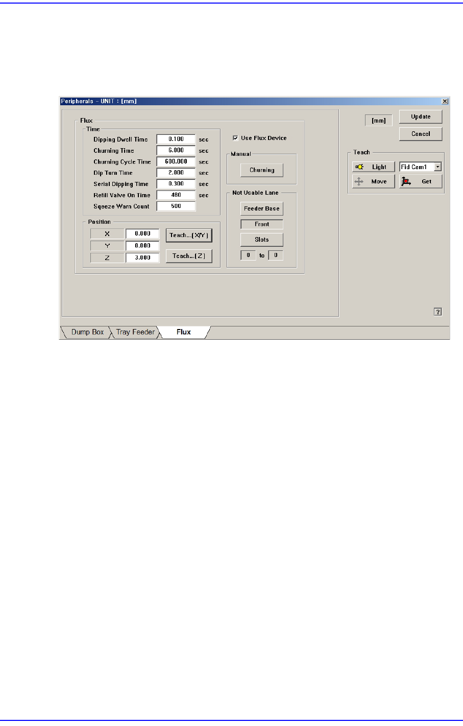
Sets the data related to the flux module. If this tab is selected, the following dialog box is
indicated.
Figure15.9 “Tray Feeder” Tab Dialog Box
<Time> group
This is enabled when the <Use Flux Device> on the right is selected. It sets the item
related to the movement of the flux module.
<Dipping Dwell Time> edit box
Refers to the delay time after the part contacts with the disk of the flux module in
order to apply flux on the part. (Dipping Delay Time)
<Churning Time> edit box
Refers to the period of time required for disk rotation when the flux module is
operated manually.
<Churning Cycle Time> edit box
Refers to the rotating cycle of the flux module disk for flux churning.
<Dip Turn Time> edit box
Refers to the period of time required for flux churning for automatic production.
(Squeezing Time)
<Serial Dipping Time> edit box
Refers to the minimum period of time required for flux churning when several
heads are dipped continuously during automatic production.
<Refill Valve On Time> edit box
Refers to the flux replacement cycle. If it is set to ‘0’, the warning message is not