DECAN_S1_Administrator′s_Guide(Eng_Ver1.5)_Print.pdf - 第227页
7-63 Part Registration button Set the light for the camera to reco gnize the component. Please refer to “7.1.1 Common Align Data” for more Information. <Size> group Set the Align size. <X Lead Num> edit…
7-62
Next Generation, Multi-Functional Placer DECAN S1 Administrator’s Guide
<Move> button
Used for parts recognition test by manually picking up parts.Please refer to“7.1.1
Common Align Data” for more Information.
<Test> button
Tests component recognition by using the set align data. Please refer to“7.1.1
Common Align Data” for more Information.
<Image Capture> button
Helps to specify the optimum lighting value. The lighting is gradually changed
automatically and the images are saved. The user can check the best image and
identify the optimum lighting value. Please refer to “7.1.1 Common Align Data” for
more Information.
<Auto Teach> button
Automatically finds out the component align data. Please refer to“7.1.1 Common
Align Data” for more Information.
7.1.3.2. QFP component data setting
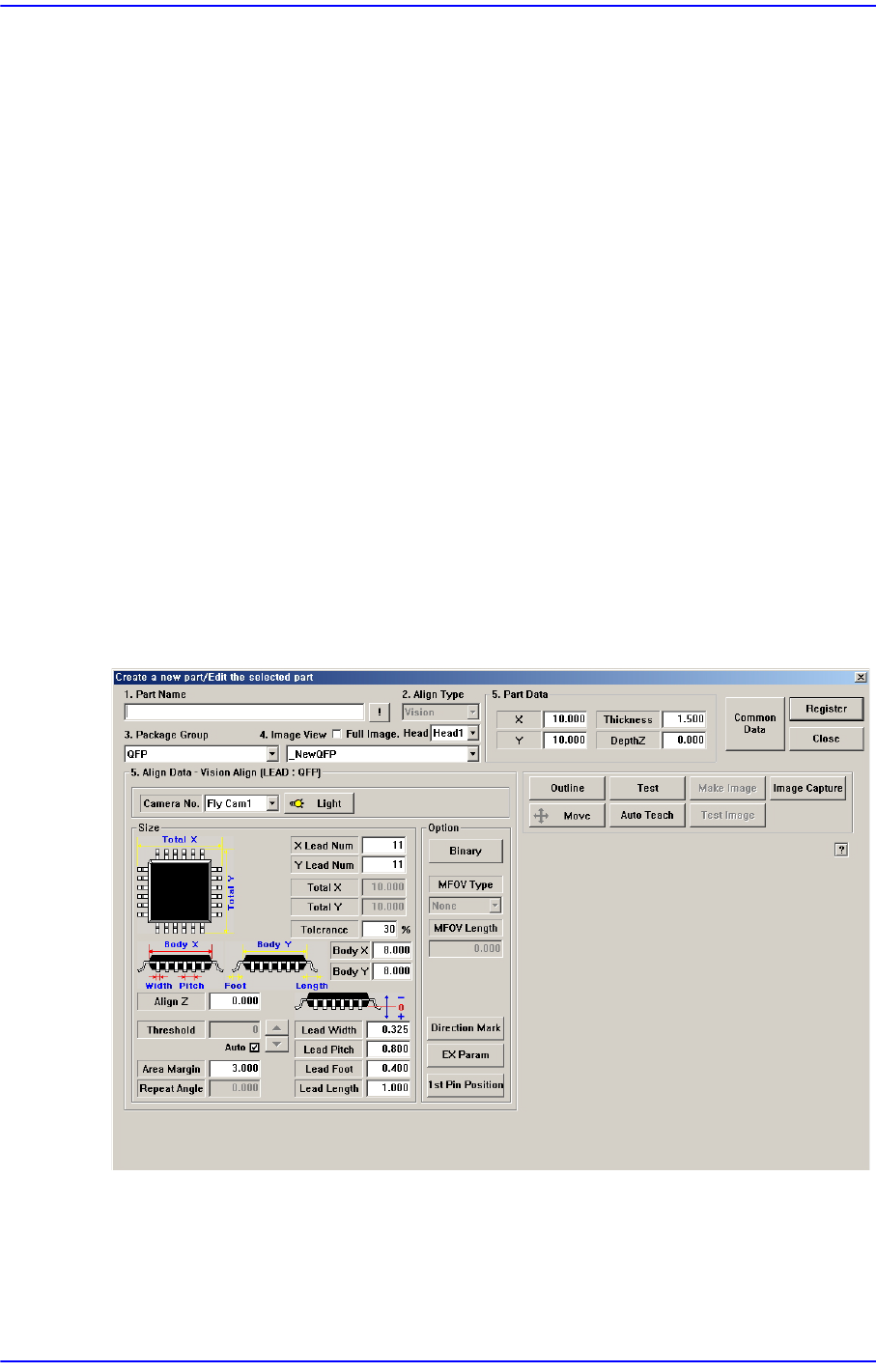
Set the align data for QFP components.
Figure7.22 “Package Group =QFP” dialog box
<Camera No.> combo box
Select the camera to recognize the component. Please refer to “7.1.1 Common Align
Data” for more Information.
7-63
Part Registration
button
Set the light for the camera to recognize the component. Please refer to“7.1.1
Common Align Data” for more Information.
<Size> group
Set the Align size.
<X Lead Num> edit box
Set the number of leads on the X direction.
<Y Lead Num> edit box
Set the number of leads on the Y direction.
<Total X> edit box
Displays the size of the whole component in X direction. It is calculated and
displayed when <Body X> and <Lead Length> are determined. ( <Body X>
+<Lead Length> *2)
<Total Y> edit box
Displays the size of the whole component in Y direction. It is calculated and
displayed when <Body Y> and <Lead Length> are determined. ( <Body Y>
+<Lead Length> *2)
<Tolerance> edit box
Set the tolerance of the component data. Default is 30%.
<Body X> edit box
Set the component size in X direction.
<Body Y> edit box
Set the component size in Y direction.
<Lead Width> edit box
Set the width of lead.
<Lead Pitch> edit box
Set the lead pitch.
<Lead Foot> edit box
Set the length of the lead that touches the surface
<Lead Length> edit box
Set the length of the lead viewed in the Align Camera.
For other setups, please refer to “7.1.1 Common Align Data”.
<Option> group
Set the Align Option data. Please refer to“7.1.1 Common Align Data” for more
7-64
Next Generation, Multi-Functional Placer DECAN S1 Administrator’s Guide
Information.
<Move> button
Used for parts recognition test by manually picking up parts.Please refer to “7.1.1
Common Align Data” for more Information.
<Test> button
Tests component recognition by using the set align data. Please refer to “7.1.1
Common Align Data” for more Information.
<Image Capture> button
Helps to specify the optimum lighting value. The lighting is gradually changed
automatically and the images are saved. The user can check the best image and
identify the optimum lighting value. Please refer to“7.1.1 Common Align Data” for
more Information.
<Auto Teach> button
Automatically finds out the component align data. Please refer to“7.1.1 Common
Align Data” for more Information.
7.1.3.3. PLCC component data setting
Set the align data for PLCC components. Please refer to “7.1.3.5 QFP component data
setting” for more Information.
7.1.4. User IC component data setting
Set align data for User IC components. First, the basic concept behind User IC component
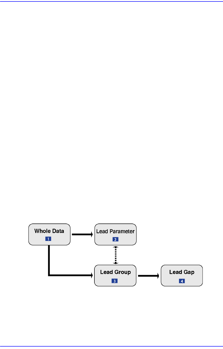
data setting is explained. Please refer to the next figure.
Figure7.23 The basic concept of User IC component data setting
1: Register overall information on the component
2: Data that have lead information on lead forms
3: Data that specify the position where the lead are converged
4: Information on the position of empty in the lead group