DECAN_S1_Administrator′s_Guide(Eng_Ver1.5)_Print.pdf - 第302页
9-8 Next Generation, Multi-Functional Plac er DECAN S1 Administrator’s Guide <Position T ype> combo box Select the num ber of fiduci al marks. A v ailable numbers of fiducial marks are as follows. None: No fiduci…
9-7
Step Programming
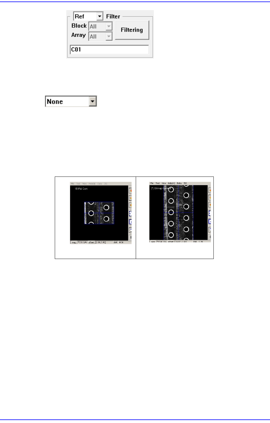
<Filtering> button
Indicates only the placement point that is filtered according to the condition
selected from the <Filter> combo box in the “Steps” dialog box.
button
<None>
The panorama recognition function of the PCB vision is not used.
<Panorama>
It is possible to display the PCB shape on one vision window by performing split
recognition of the PCB shape and composing the split images into one.
<Insert 1Line> button
Adds a new placement point before the line (placement point) currently selected from
the <Grid>.
<2Pt. Teach> button
When a placement position is set, performs the function of teaching 2 corner points,
calculating the center point and using it as the placement point. Please refer to “8.1.1
Feeder Base”<2Pt. Teach…> button for more information.
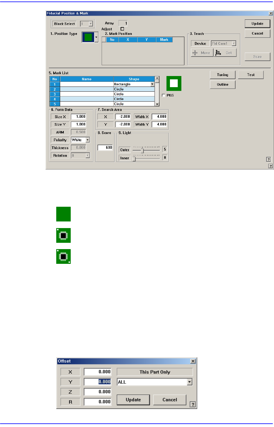
<Fiducial…> button
If the placement point has a fiducial mark, sets the fiducial mark data. Closes the
dialog box without saving the changed contents.
None
Panorama
9-8
Next Generation, Multi-Functional Placer DECAN S1 Administrator’s Guide
<Position Type> combo box
Select the number of fiducial marks. Available numbers of fiducial marks are as
follows.
None: No fiducial mark.
1 Part: 1 fiducial mark for placement point adjustment.
2 Part: 2 fiducial marks for placement point adjustment.
Please refer to “6.3. Fiducial Mark Setup” for more information.
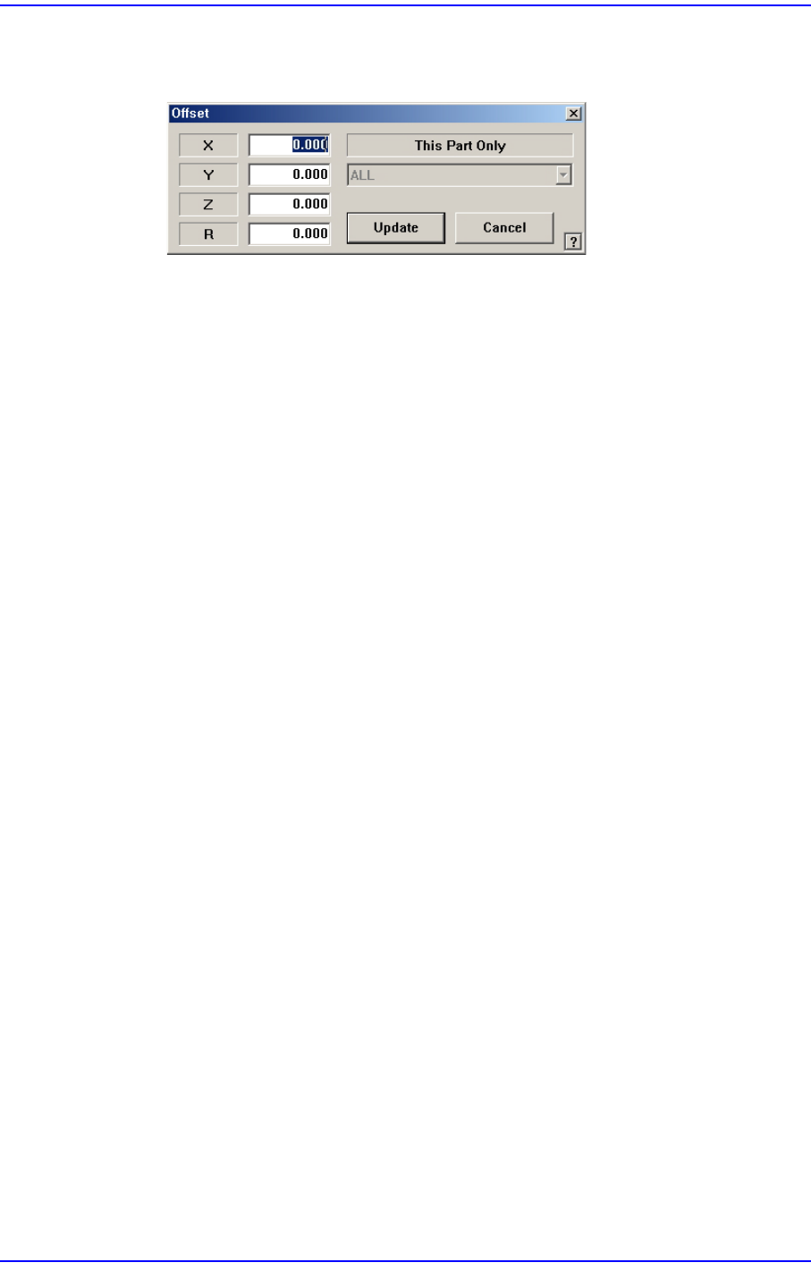
<Offset…> button
Adds the offset value to the position of placement point. Before executing this
function, X column or Y column or Z column or R column or the line to add the offset
value must be selected in the grid. When this button is clicked on, the following dialog
box is displayed.
<When one of X, Y, Z, and R is selected>
Apply the offset value to the selected part.
9-9
Step Programming
<When the row is selected>
Apply the offset value to all parts.
<X> edit box
Set the X offset value.
<Y> edit box
Set the Y offset value.
<Z> edit box
Set the Z offset value.
<R> edit box
Set the R offset value.
<OK> button
Closes the dialog box and adds the set offset value to the selected line in the grid.
<Cancel> button
Ignores the set offset value and closes the dialog box
<Adjust…> button
It is a function used to change the PCB step coordinate or to check and adjust the gap
between the previous fiducial mark coordinate and the current fiducial mark
coordinate to use the previous step coordinate when the backup table is down
accidentally.
<Clear Cycle> button
Initialize the placement cycle.
<Refresh Feeder> button
When the feeder setup has been changed in the “feeder” dialog box, clicking this
button will allow the feeder changed in the “Step” dialog box to be set up again.
<Refresh Nozzle> button
When the nozzle arrangement on the ANC has been changed, clicking this button will
allow the nozzle changed in the “Step” dialog box to be set up again.
<Place Parts> button
This function is provided to perform testing in preparation for operation or to
compliment some placement points during operation. It is used to place parts at the
placement point selected from the <Step> dialog box.