DECAN_S1_Administrator′s_Guide(Eng_Ver1.5)_Print.pdf - 第466页
14-84 Next Generation, Multi-Functional Plac er DECAN S1 Administrator’s Guide 7. Save the data by clic king the <Upd ate> button.
14-83
Machine Calibration
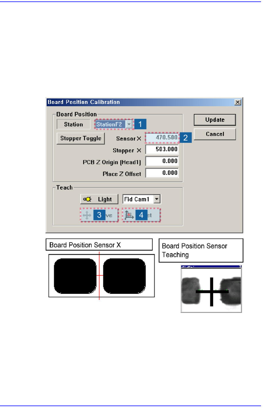
14.3.9. Board Position Calibration
Teach the stopper position in the conveyor installation area and the X position of the
sensor.
The following is the board position calibration procedure.
1. Select the edit box for the <Sensor X> using the mouse and move the downward
camera (Fiducial Camera) to the position of Sensor X by clicking the <Move> button.
2. Perform teaching of the exact position using the teaching box. Enter the precise
coordinates for ‘Sensor X’ by pressing the <Get> button of the teaching box.
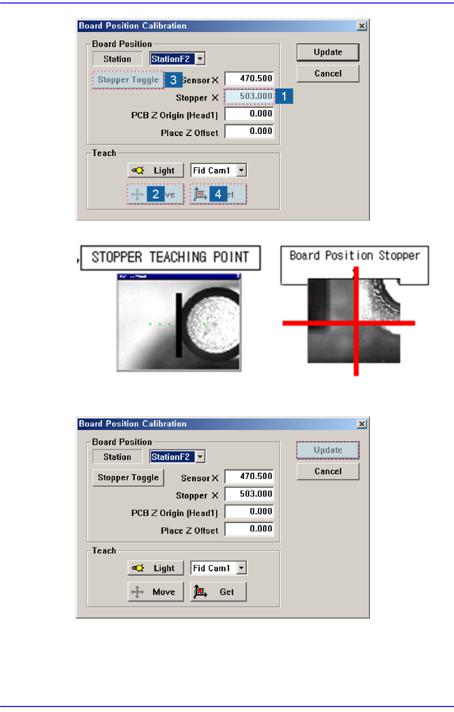
3. Select the <Stopper X> combo box using the mouse and then select the stopper to
teach and click the <Move> button, move fiducial Camera to position of Stopper X.
4. Click the <Stopper Toggle> button in the left of the <Stopper X> edit box first to move
the stopper up and then teach the stopper position correctly using the teaching box.
5. Click the <Get> button to enter the coordinates in the <Stopper X> edit box.
6. Click the <Stopper Toggle> button to move down the stopper.
14-84
Next Generation, Multi-Functional Placer DECAN S1 Administrator’s Guide
7. Save the data by clicking the <Update> button.
15-1
System Setup
Chapter15. System Setup
Describe system setups except for the calibration items mentioned in the preceding
chapter.
The items on this menu are setup at the time of shipment. Therefore, do not perform
“Calibration System Setup” except when setup is required for the maintenance of the
machine.
Warning hanging the set up status by an unauthorized user could
damage the equipment or result in personal injury.
Unauthorized user must not change the set up status of the
equipment.
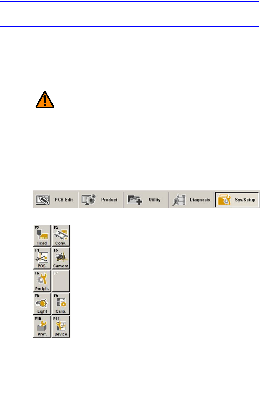
When a submenu of the <Sys. Setup> menu is selected, corresponding dialog box is
displayed on the screen. While the corresponding dialog box is displayed, selecting the
menu once more activates the dialog box.
Figure15.1 When the Sys. Setup menu is selected
Figure15.2 Submenus of the Sys. Setup menu