DECAN_S1_Administrator′s_Guide(Eng_Ver1.5)_Print.pdf - 第150页
6-36 Next Generation, Multi-Functional Plac er DECAN S1 Administrator’s Guide The image viewed through the SM V ision window is composed of each pixel. Each pixel has a unique va lue between 0 and 255 ac cording to the s…

6-35
Board Definition
<1.Use> check box
Set whether to use the Accept Mark.
<2. Mark Position> group
The Accept Mark position teaching result is inputted.
<3. Teach> group
Teach the Accept Mark position.
Procedure to teach the Accept Mark
Select the fiducial camera corresponding to the workstation to which a PCB is
loaded.
Click the <<Move> button to move to the position of the currently set Accept
Mark.
Perform adjustments so that the Accept Mark center falls on the crosshair center in
the SMVision window.
Click the <Get> button to input the current coordinate.
<4. Mark Type> group
Select the color of Accept Mark. Available mad mark colors are as follows;
Black: the mark appears darker than the surrounding.
White: the mark appears brighter than the surrounding.
<5. Search Area> group
Set the area to test the Accept Mark. The purpose is to limit the testing area when
recognition is interfered due to a shape similar to the mark near the mark.
<Width X> edit box
Set the range to test in X axis direction. In general, set to 6mm.
<Width Y> edit box
Set the range to test in Y axis direction. In general, set to 6mm.
<6. Mark Size> group
The size of the Accept Mark is displayed.
<Size X> edit box
The horizontal size of the Accept Mark is displayed. The size is changed based on
the value set in the <Width X> edit box of <5. Search Area> group.
<Size Y> edit box
The vertical size of the Accept Mark is displayed. The size is changed based on
the value set in the <Width Y> edit box of <5. Search Area> group.
<7. Parameter> group
<Threshold> edit box
6-36
Next Generation, Multi-Functional Placer DECAN S1 Administrator’s Guide
The image viewed through the SM Vision window is composed of each pixel.
Each pixel has a unique value between 0 and 255 according to the seen degree of
brightness. Here, ‘Threshold Value’ indicates the border value deciding whether
each pixel should be recognized in white or black. That is, setup the limitation for
deciding if the image pixel should be black or white when checking a bad mark.
For example, if accept mark setup is “Black” and the <Threshold> value is 100, all
values under 100 in the vision image are recognized as black. And if <Accept
mark Logic> is “White” and the <Threshold> value is 100, all values over 100 in
the vision image are recognized as white.
<Real Display/Binary> button
Shows the image seen through the SMVision in real display to which threshold is
not applied, or in the image (Binary) to which threshold is applied as recognized
by MMI.
<Light> group
Set the lighting value when testing the Accept Mark. In general, set to 7. However,
adjust it properly according to the condition of the PCB and accept mark.
<Test> button
Tests the mark by using the set mark data. The user can check whether the set
mark data is correct. When the test is successful, the following message box is
displayed..
Caution If you move to another screen while editing the “Board”
dialog box, the edited data is saved automatically
<Update> button
Save the Accept Mark data and close the “Accept Mark Position” dialog box.
<Cancel> button
Close the “Accept Mark Position” dialog box without saving the Accept Mark data.
6.6. 2D Barcode
6.6.1. Configuration
Allows a user to know the model information of the PCB loaded into the machine by
recognizing the 2D barcode on the PCB and manage the production history by interlocking
PCB with the Lot Tracking System (LTS).
In addition, it is possible to save production time by transmitting the information from the
board recognized by the first equipment to the next equipment.
6-37
Board Definition
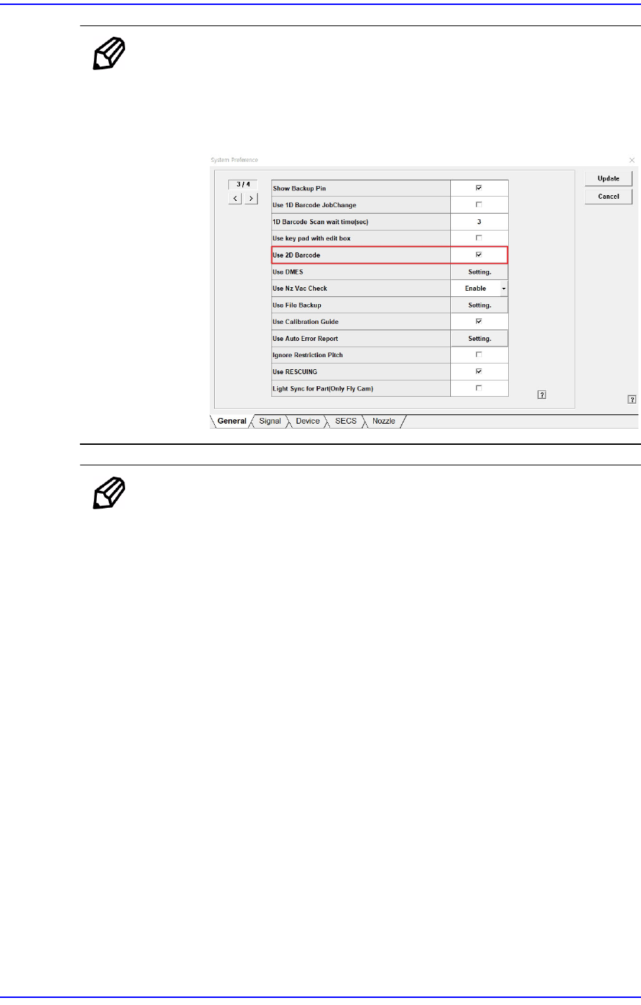
Memo To activate the <Bar Code> menu, check the <Use 2D Barcode>
checkbox in <Sys.Setup>.
Setup path: <Sys.Setup> → <Pref.> → <General> → <Use 2D
Barcode>
Memo When using 1D barcode or using no barcode (only using the IT
functions), set as follows.
When using 1D barcode
In the [Option] item of the “C:\SmartSM\bin\SmartSM.ini” file,
set the QFEEDER to 1 and the LotTracking to 1, and Usebarcode
to 0.
When using no barcode (only using the IT functions)
In the [Option] item of the “C:\SmartSM\bin\SmartSM.ini” file,
set the IQFEEDER to 1 and the LotTracking to 0, and
Usebarcode to 0.