DECAN_S1_Administrator′s_Guide(Eng_Ver1.5)_Print.pdf - 第526页
15-60 Next Generation, Multi-Functional Plac er DECAN S1 Administrator’s Guide This is selected when applyi ng the feed angle (R) and mo unting angle (Part R) of the stick or tray feeder to the parts data regist ered in …
15-59
System Setup
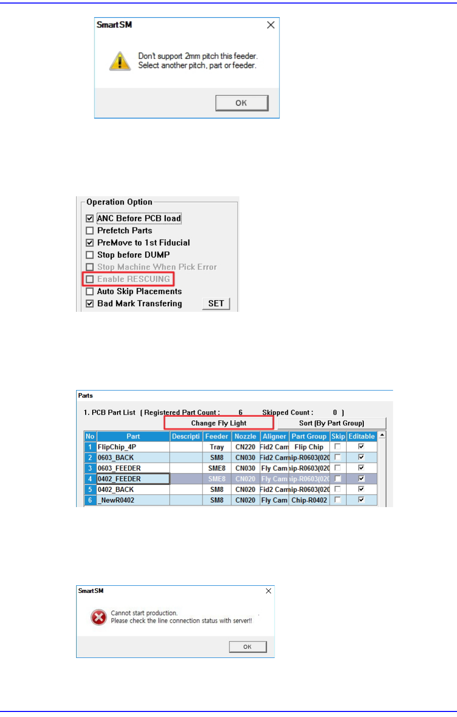
<Use RESCUING> check box
When this check box is ticked, the <Enable RESCUING> check box is activated in the
<Operation Option> area of the “Product” menu. For details on this function, refer to
“13.1.2. Option Setting”.
<Light Sync for Part(Only Fly Cam)> check box
This is used when it is necessary to collectively change the lighting value of parts that
use the fly camera. When this check box is ticked, the <Change Fly Light> button is
activated in the “Parts” window.
<PNP Connection Check> check box
Checks whether the machine and PNP are connected before starting production.
Starting production with the machine not connected to the PNP will display an error
message.
<Use Pickup Offset Sync> check box
15-60
Next Generation, Multi-Functional Placer DECAN S1 Administrator’s Guide
This is selected when applying the feed angle (R) and mounting angle (Part R) of the
stick or tray feeder to the parts data registered in the feeder. When this check box is
ticked, each time the PCB file is opened, the feed angle and mounting angle of the part
are changed to the feeder data.
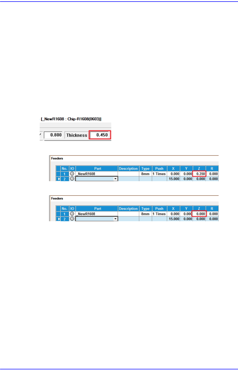
<Auto Apply Pick Up Height> combo box
When this check box is ticked, the pickup height of the part is automatically reflected
to the feeder Z value, but only for feeders whose reel type is Paper. (Pickup height of
the part: Thickness of the part - 0.1mm)
When changing the model, it takes a long time to set the pickup height of the part
when the number of tape feeders is large. At this time, you can shorten the model
change time by using this function.
[e.g.: Chip parts with a thickness of 0.450]
[Auto Apply Pick Up Height = Use]
[Auto Apply Pick Up Height = Not Use]
<Apply Prev Slot Data(Only Tape Feeder> check box
When producing two models (A, B) with the same placement of tape feeders using
similar components, this function is used to apply the feeder information (X, Y, Z, R,
etc.) of an already taught Model A to the feeder information of Model B.
By using this function, no unnecessary teaching operation will be performed when
Model B is produced, and the preparation time can be shortened.
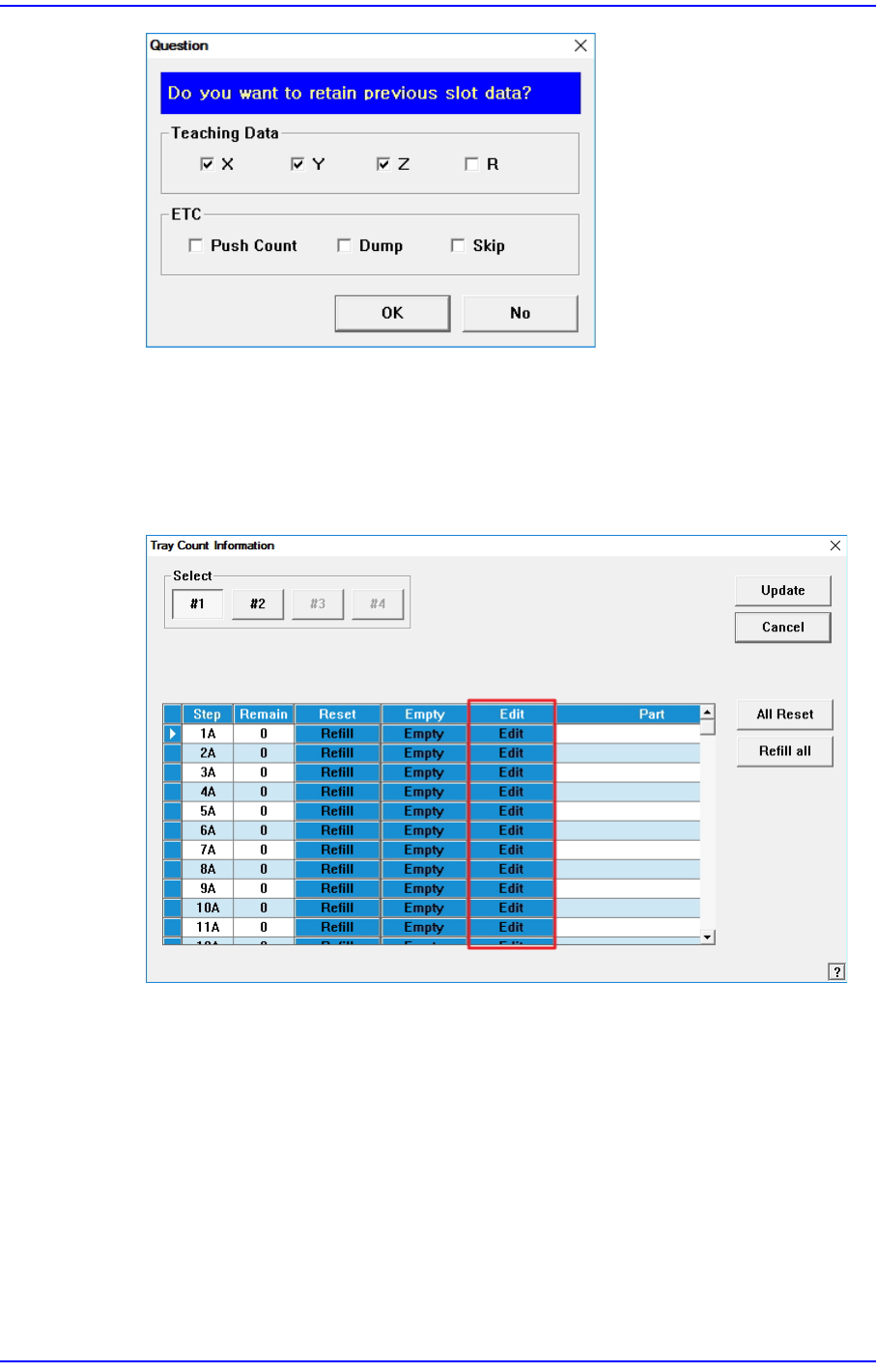
When this check box is ticked, the following dialogue box will be displayed when
opening the PCB file of Model B.
15-61
System Setup
Select the items to be applied to the feeder information of Model B, and then click the
<OK> button.
<Use tray manage by pocket> check box
When this check box is ticked, the <Edit> column is activated in the “Tray Cnt
Information” window. For details on this function, refer to “13.6. T/F Cnt”.
<Use Multi-Vendor> check box
This function is used to produce PCBs by using parts made by several manufacturers
for a part.
Allows work to be automatically performed using sub parts when placing them on a
PCB after registering them.
Selecting this check box activates the <Sub Part> column in the “Feeder” window.