DECAN_S1_Administrator′s_Guide(Eng_Ver1.5)_Print.pdf - 第363页
13-11 Production Setup Caution This function allows the placement t o be simply performed continuously. If interference is expected in the future between the skipped part and the n earby placed parts while performing pla…

13-10
Next Generation, Multi-Functional Placer DECAN S1 Administrator’s Guide
conveyor.
<Operation Option> group
Set the options related to placement.
<ANC before PCB load> check box
Selected so that the PCB stands by after replacing the nozzle before the PCB is
fed.
<Prefetch Parts> check box
In the case of the equipment with dual gantries, when the corresponding gantry
cannot work continuously due the shortage of parts in the feeder that has supplied
parts to any one of the gantries, it selects the function to improve the productivity
temporarily with another gantry performing the work instead.
For this function the <Auto Skip Placements> check box shall be selected in the
<Operation Option> group. This function can be used in the SM411 model.
<PreMove to 1st Fiducial> check box
While the PCB is being put into the working station, MMI move the fiducial
camera to the fiducial mark position and have it stand by.
<Stop before DUMP> check box
Selected so that the machine stops before dumping the part to the dump box when
a part recognition error occurs.
< Stop Machine When Pick Error> check box
There is a PCB in which small chips are placed underneath the large part such as a
shield cap.
In cases where the machine is equipped with a dual gantry that works on such
PCB, since each gantry performs work individually, a chip must be placed first.
However, even though the chip cannot be mounted since an error occurred while
picking it up, a situation occurs in which the rear gantry must place the shield cap.
As such, if the rear gantry places the part that is placed on a part such as the shield
cap earlier than the front gantry, the part underneath cannot be placed. Therefore,
when a pickup error occurs, this function stops the machine immediately.
<Auto Skip Placements> check box
Even when a specific part has run short during automatic production, placement is
continuously performed on the remaining placement points, generating a warning
message.
13-11
Production Setup
Caution This function allows the placement to be simply performed
continuously. If interference is expected in the future
between the skipped part and the nearby placed parts while
performing placement, release this function.
<Bad Mark Transferring> check box
This function is used when a scanner made by D-TEK is used. For more details
regarding this, contact us.
<Self Board Fiducials> check box
When the machine operation mode is 'Join', select this check box in order to
increase the part placement accuracy by having the front and rear gantries
recognize the fiducial marks on the PCB respectively.
<Soft Ground> check box
When the machine is installed at a location of soft ground, selecting this check box
will reduce the vibration and noise that occurs due to instantaneous acceleration of
the XY axes.
<PCB Transfer Speed> combo box
Used to adjust the PCB feeding speed. When the PCB is heavy, if it is selected at too
high speed, the conveyor belt may not feed the PCB sufficiently with the belt rotating
while slipping. The default selection is Middle. Adjust the speed appropriately, if
necessary.
Fastest: very high speed
Fast: high speed
Middle: medium
Slow: low speed
<Speed> slide bar
Select the driving speed of the XY axis driving motor.
<Z Axis Mount Delay> slide bar
Works after adding the defined value in the slider bar to the placement delay value
setup in the common data at the time of part registration. This value is applied only to
Z-axis.
<Progressive Product> check box
This function can only be used when the conveyor type is Sigle Lane and a docking
cart is used.
This function is used to proceed with production with one equipment unit
using two PCB files with different steps and feeder arrangements on one PCB.
13-12
Next Generation, Multi-Functional Placer DECAN S1 Administrator’s Guide
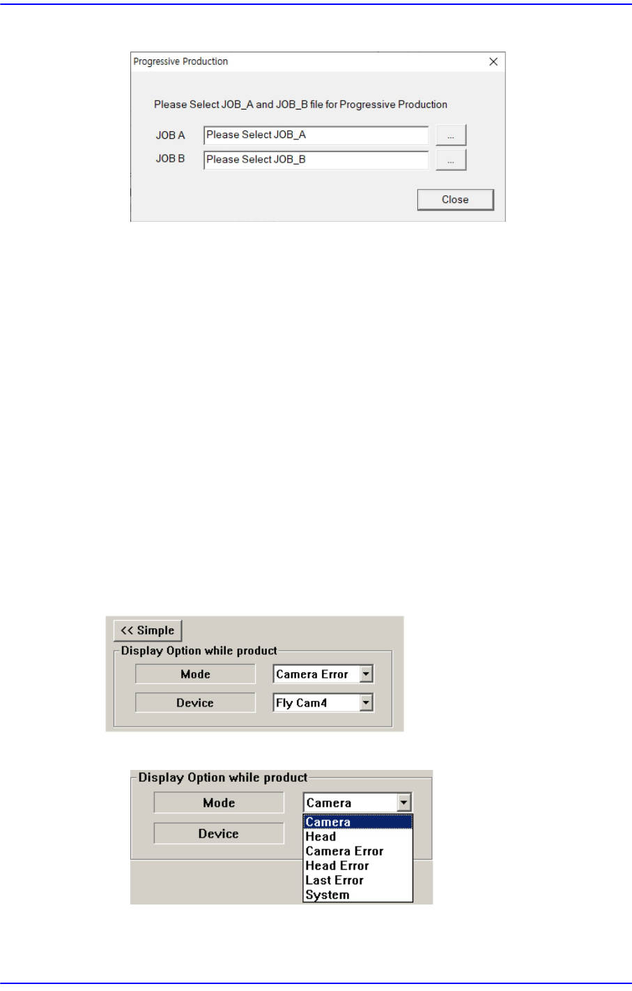
<SET> button
Scenarios for using this feature are as follows:
1)Prepare 2 PCB files that meet the above conditions.
2)Select the <Product>-<Option Setting>-<Progressive Product> check box and select
the <SET> button.
3)Load the PCB files you want to produce in JOB A and JOB B.
4)Open the PCB file to be produced first and start production.
At this time, check if it is displayed as JOB_A: the name of the PCB to be
produced first in the PCB information on top of MMI after downloading RT.
5)When PCB production is completed, use the Docking Change Dialog to connect the
docking cart to be used on the second PCB and select Continue.
At this time, check if it is displayed as JOB_B: the name of the PCB to be
produced second in the PCB information on top of MMI after downloading RT.
<Detail> button
This button is used to select the image viewed in the SMVision window during PCB
production.
<Mode> combo box
Camera
Selected when looking at the image of a specific camera. Select the