DECAN_S1_Administrator′s_Guide(Eng_Ver1.5)_Print.pdf - 第496页
15-30 Next Generation, Multi-Functional Plac er DECAN S1 Administrator’s Guide 5. After unchecking the <Manual>check box in the <3. T o ol Setting> group, click the <Prepare T est / Mapping> button.
15-29
System Setup
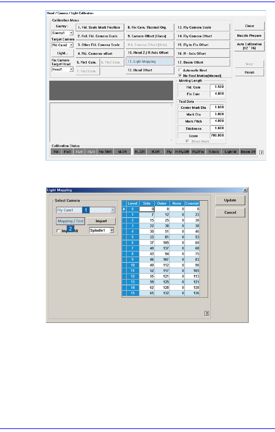
3. After selecting the camera for which light mapping is to be performed in the <Select
Camera> group, click the <Mapping/Test> button.
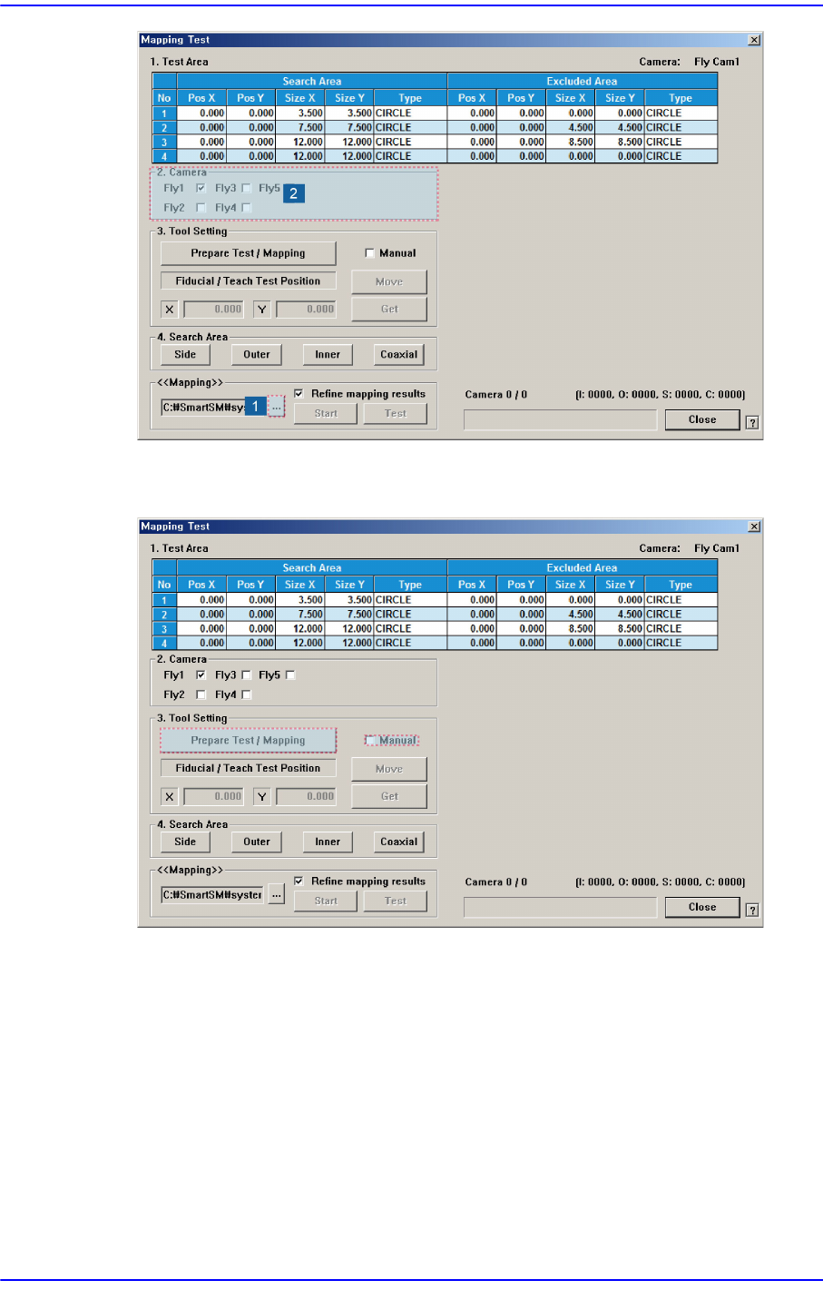
4. Click the <...> button in the <<Mapping>> group to select the file for calibration.
Then select the camera to be calibrated in the <2. Camera> group.
15-30
Next Generation, Multi-Functional Placer DECAN S1 Administrator’s Guide
5. After unchecking the <Manual>check box in the <3. Tool Setting> group, click the
<Prepare Test / Mapping> button.
15-31
System Setup
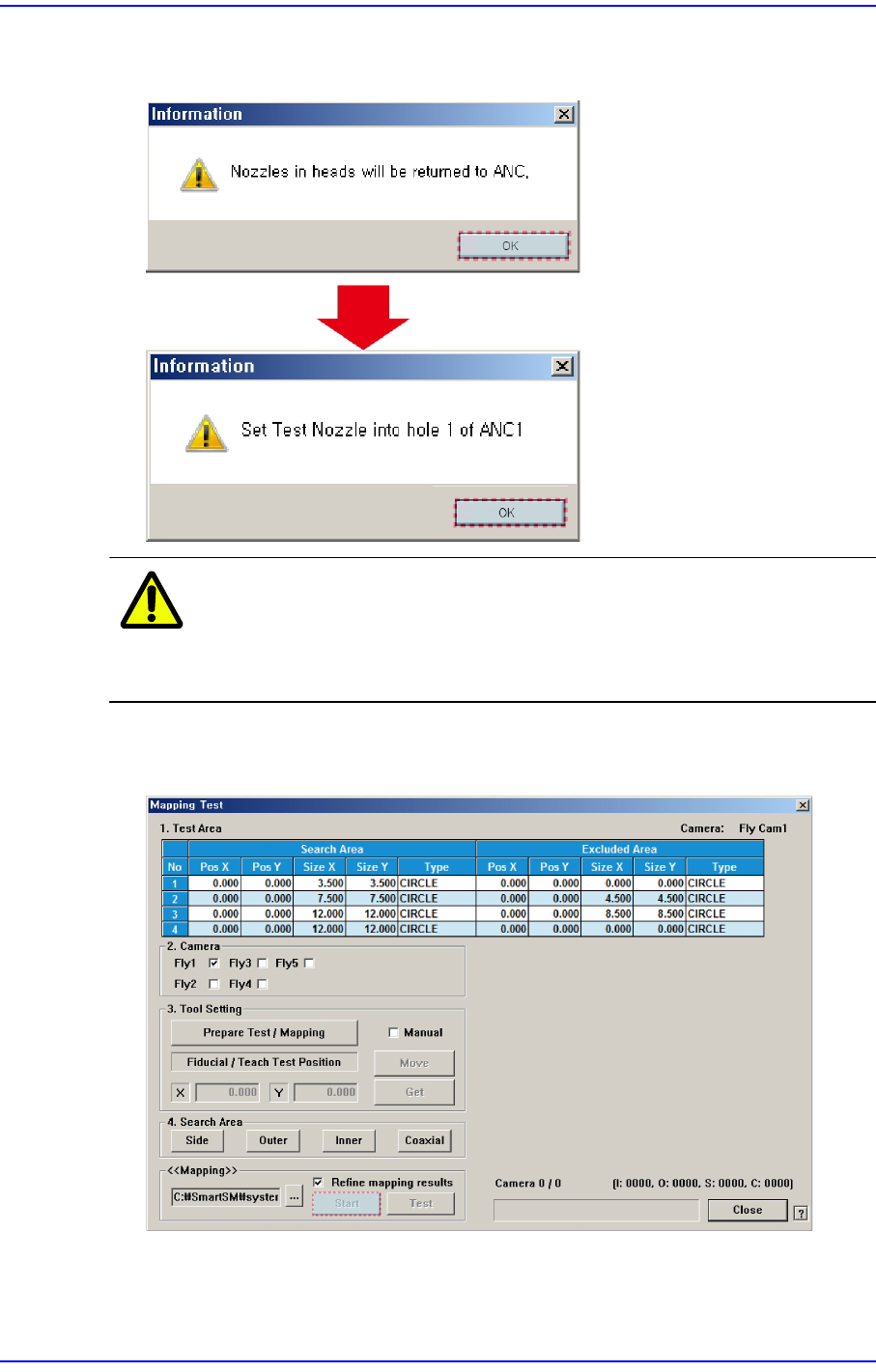
6. Click the <OK> button in the following order to remove all nozzles installed on the
head. Then insert the nozzle for the fly camera test into the No. 1 hole of the ANC.
Caution If the acrylic door is open, it affects the lighting during light
mapping. Therefore, close the acrylic door before
performing light mapping.
7. Once the <Prepare Test / Mapping> is completed, click the <Start> button in the
<<Mapping>> group to perform light mapping.