00195722-0102_UM_X-Serie_SR605_EN.pdf - 第125页
User Manual SIPLACE X-Series 3 Technical data for the machine From software version SR.605.xx 07/2008 EN Edition 3.5 Placement head 125 3.5.2 12-segment Collect&Place head for high-speed placement 3 Fig. 3.5 - 3 12-s…

3 Technical data for the machine User Manual SIPLACE X-Series
3.5 Placement head From software version SR.605.xx 07/2008 EN Edition
124
3.5.1.2 Technical data
3
3
3
3
3.5.1.3 Sensor for the component reject bin
PLEASE NOTE 3
If a 20-segment Collect&Place head is used, then we recommend that you install the optional
sensor for the component reject bin. (See also Section 6.5, page 431)
Range of components
a
a) Please note that the component range that can be placed is also affected by the pad geometry, the cus-
tomer-specific standards and the packaging tolerances.
01005 to 2220, Melf, SOT, SOD
Component specification
max. height
min. lead pitch
min. lead width
min. ball pitch
min. ball diameter
min. dimensions
max. dimensions
max. weight
4 mm
0.25 mm
0.1 mm
0.4 mm
0.2 mm
0.4 x 0.2 mm²
6 x 6 mm²
1 g
Programmable set-down force, variable increments 1.5 ± 0.5 N
2.0 ± 0.5 N
3.5 ± 1 N
4.5 ± 1 N
Nozzle types 10xx, 11xx, 12xx
X/Y accuracy ± 41 μm/3σ, ± 55 μm/4σ
Angular accuracy ± 0.5°/3σ, ± 0.7°/4σ
Component range 95%
CO camera type 23
Illumination level 5
Possible illumination level settings 256
5
User Manual SIPLACE X-Series 3 Technical data for the machine
From software version SR.605.xx 07/2008 EN Edition 3.5 Placement head
125
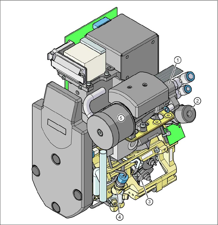
3.5.2 12-segment Collect&Place head for high-speed placement
3
Fig. 3.5 - 3 12-segment Collect&Place head - Function groups, part 1
3
(1) Vacuum generator
(2) Turning station, DP axis
(3) Star with 12 sleeves, star axis
(4) Forced air valve
(5) Silencer
3 Technical data for the machine User Manual SIPLACE X-Series
3.5 Placement head From software version SR.605.xx 07/2008 EN Edition
126
3
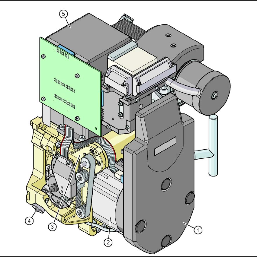
Fig. 3.5 - 4 12-segment Collect&Place head - Function groups, part 2
3
(1) Intermediate distributor board (beneath the cover)
(2) Star drive - DR motor
(3) Z axis motor
(4) Valve adjustment drive
(5) C&P component camera, type 28 (18 x 18) digital or type 29 (27 x 27) digital, high resolution
3.5.2.1 Description
The 12-segment Collect&Place head works on the Collect&Place principle. This means that,
within each cycle, twelve components are picked up by the placement head, are optically centered
on the way to the placement position and are rotated into the required placement angle. They are