00195722-0102_UM_X-Serie_SR605_EN.pdf - 第236页
3 Technical data for the machine User Manual SIPLACE X-Series 3.12 SIPLACE HF component trolley From software ver sion SR.605.xx 07/2008 EN Edition 236 3.12.1 1 Used t ape channel on the SIPLAC E HF component tr olley do…
User Manual SIPLACE X-Series 3 Technical data for the machine
From software version SR.605.xx 07/2008 EN Edition 3.12 SIPLACE HF component trolley
235
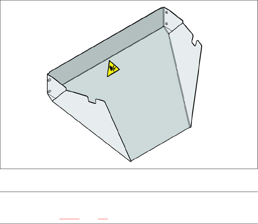
3.12.10 Used tape chute, SIPLACE HF
3
Fig. 3.12 - 9 Used tape chute for SIPLACE HF
PLEASE NOTE 3
The SIPLACE HF used tape chute can only be installed on the SIPLACE HF component trolley
docking unit (see Fig. 5.11 - 6, page 364.
3 Technical data for the machine User Manual SIPLACE X-Series
3.12 SIPLACE HF component trolley From software version SR.605.xx 07/2008 EN Edition
236
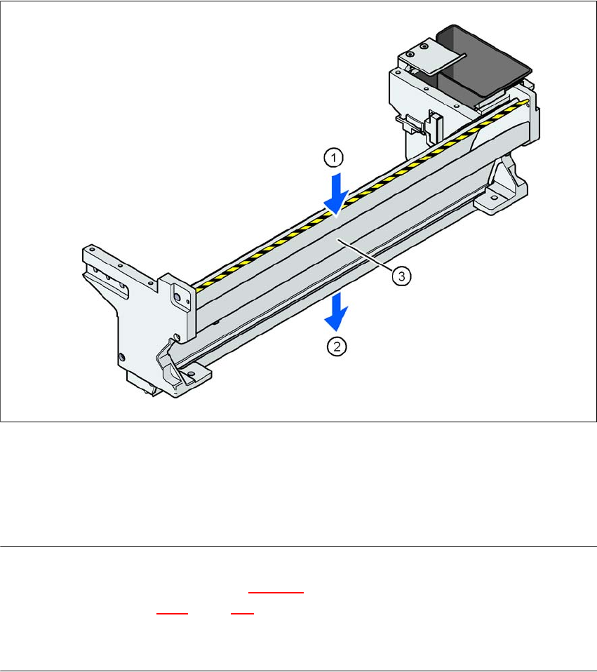
3.12.11 Used tape channel on the SIPLACE HF component trolley docking unit
In the standard version, the used tape channel can guide component tapes with a maximum
pocket height of 17 mm to the pneumatic tape cutter.
3
Fig. 3.12 - 10 Used tape channel on the SIPLACE HF component trolley docking unit
(1) Inlet slot for the used tapes
(2) Outlet slot for the used tape above the pneumatic tape cutter
(3) Dividing plate for tapes < 17 mm (can be removed for tapes > 17 mm)
PLEASE NOTE
– The separating plate (item 3 in Fig. 3.12 - 10
) can be removed for tape pockets higher than
17 mm (see Section 4.6.2
, page 316).
→ Do not position feeder modules with shallow pockets immediately beside feeder modules with
deep pockets. The used tapes could overlap and build up.
User Manual SIPLACE X-Series 4 Setting up and commissioning
From software version SR.605.xx 07/2008 EN Edition 4.1 Transport and Delivery Configuration
237
4 Setting up and commissioning
4.1 Transport and Delivery Configuration
4.1.1 Shipping packaging
Within Europe, the placement machine and component trolleys will be shipped on two wooden
pallets, packaged in plastic film. Outside Europe, the machine and component trolleys are sup-
plied in wooden crates.
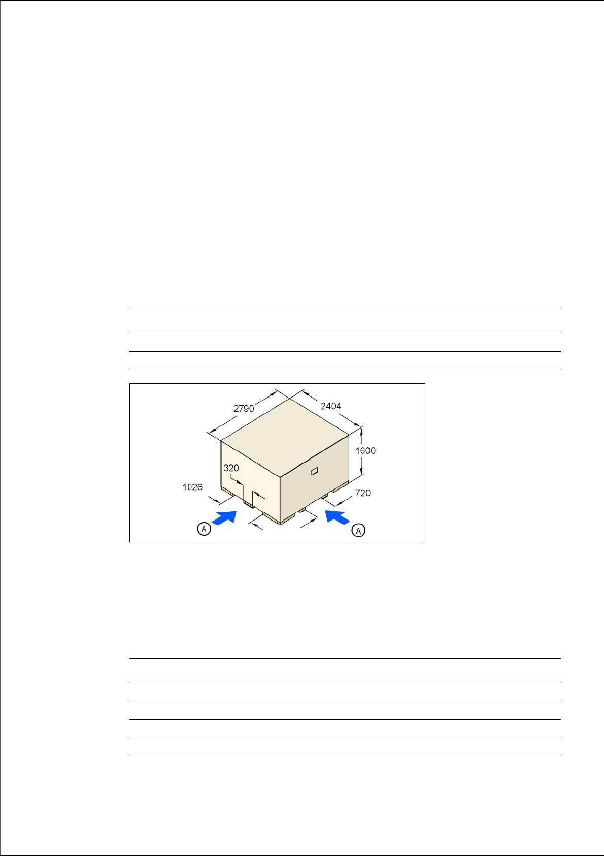
4.1.1.1 Dimensions of the shipping packaging
The dimensions of the pallets and wooden crates are listed in the following table:
4
Fig. 4.1 - 1 Transport crate - dimension in millimeters
(A) Fork-lift attachment points
4.1.1.2 Weight of the machine prepared for dispatch
The following table contains the weights of the machines prepared for dispatch, including packag-
ing.
Machine Component trolley
Pallet 2790 x 2404 mm² 2060 x 1350 mm²
Wooden crate 2790 x 2404 x 1600 mm³ 2060 x 1350 x 1300 mm³
Machine Dispatch within Europe Dispatch overseas
X2 3836 kg 4336 kg
X3 3980 kg 4420 kg
X4 4004 kg 4504 kg
CO trolley 470 kg 550 kg