00195722-0102_UM_X-Serie_SR605_EN.pdf - 第337页
User Manual SIPLACE X-Series 5 Tasks for the operating personnel From software version SR.605.xx 07/2008 EN Edition 5.5 Carrying o ut a walk-through inspection 337 5.5.7 Using spindles for large t ape reels → Insert spin…
5 Tasks for the operating personnel User Manual SIPLACE X-Series
5.5 Carrying out a walk-through inspection From software version SR.605.xx 07/2008 EN Edition
336
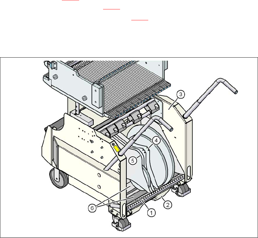
5.5.6 Inserting separating plates in the tape container
→ The separating plate has different edges and can be inserted into the tape container in two
ways. If spindles are used, the recesses for the spindles in the separating plate point upwards
(see item 4 in Fig. 5.5 - 4
). If you do not use spindles, the rounded edge of the separating
plate points up (see item 5 in Fig. 5.5 - 4
).
→ Insert the separating plates as shown in Fig. 5.5 - 4
and remember that the smallest division
of the tape container is a 2x division. This will help avoid placement errors.
→ Check that the separating plates engage in the same positions on the three guide rails. Oth-
erwise the separating plate will be offset or bent.
5
Fig. 5.5 - 4 Separating plates in the tape container
(1) Guide rail for the separating plates
(2) Waste tape container
(3) Tape container
(4) Position of the separating plate if spindles are used
(5) Position of the separating plate if no spindles are used
(6) Slide surfaces for the tape reels
User Manual SIPLACE X-Series 5 Tasks for the operating personnel
From software version SR.605.xx 07/2008 EN Edition 5.5 Carrying out a walk-through inspection
337
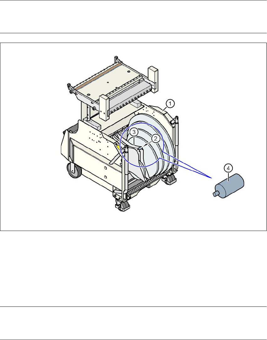
5.5.7 Using spindles for large tape reels
→ Insert spindles into the separating plates when using large tape reels on SIPLACE HF com-
ponent trolleys.
PLEASE NOTE 5
We recommend that you use spindles if the tape reel diameter exceeds 15" (381 mm)". This will
ensure that the S feeder modules operate reliably.
5
Fig. 5.5 - 5 Inserting spindles for large reels
5
(1) CO trolley
(2) Position of the spindles
(3) Separating plate
(4) Spindle (enlarged)
5
PLEASE NOTE: 5
X-series component trolleys do not generally need spindles. However, if the "Timeout" error mes-
sage occurs increasingly on the X feeder module, we recommend that you do use spindles.
5 Tasks for the operating personnel User Manual SIPLACE X-Series
5.6 Setting up the feeder modules From software version SR.605.xx 07/2008 EN Edition
338
5.6 Setting up the feeder modules
5.6.1 Notes on handling feeder modules
Feeder modules are precision devices. You should therefore handle the feeder modules with care.
→ Avoid bumping feeder modules into obstacles.
→ Do not drop the feeder modules.
→ Always use suitable tools for preventive maintenance.
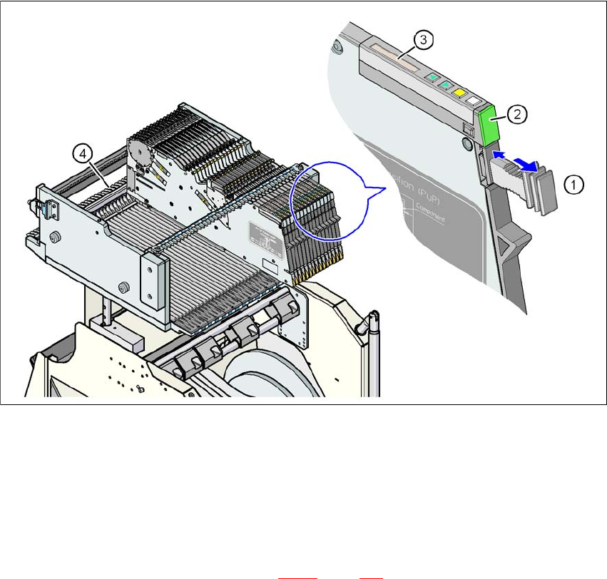
5.6.2 Removing X feeder modules from the component table
5
Fig. 5.6 - 1 Removing X feeder modules from the component table
(1) Removal handle
(2) Status display
(3) LCD display
(4) Latch for locking the X feeder modules
5
On standby, the status display (item 2 in Fig. 5.6 - 1, page 338) lights up green if the X-axis feeder
module is contained in the current set-up. If the feeder module is not contained in the current set-
up, the status display remains off.