00195722-0102_UM_X-Serie_SR605_EN.pdf - 第20页
1 Introduction User Manual SIPLACE X-Series 1.1 Description of the machine From software version SR.605.xx 07/2008 EN Edition 20 1.1 Description of the machine The SMD pl acement sys tems from the SIPLACE X-series are ch…
User Manual SIPLACE X-Series 1 Introduction
From software version SR.605.xx 07/2008 EN Edition
19
1 Introduction
These operating instructions provide a manual or reference work for operating and setting up the
placement machines for the SIPLACE
®
X-series.
The header of each chapter contains the release and software version, to which this manual ap-
plies.
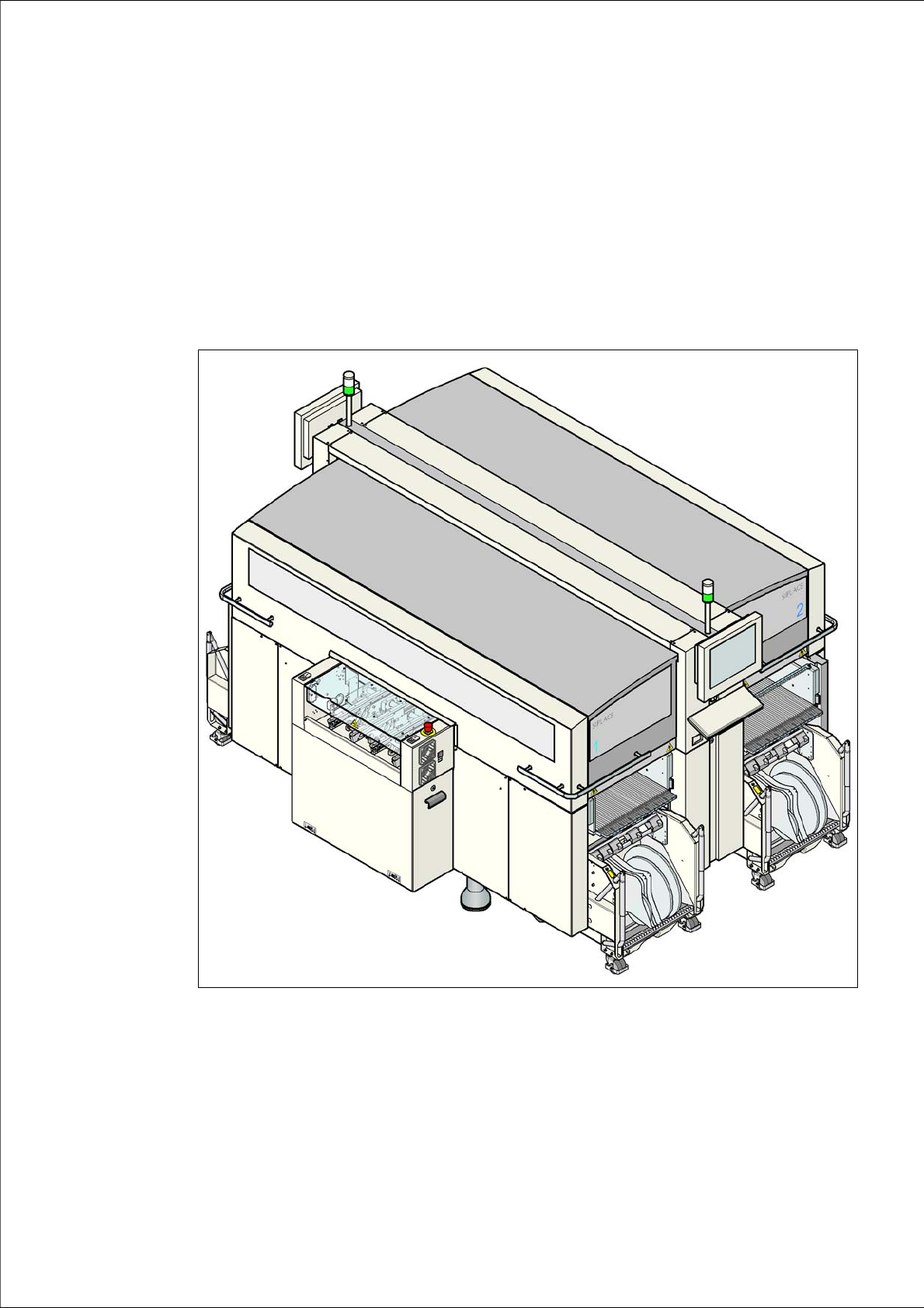
1
Fig. 1.0 - 1 SIPLACE X4 placement machine

1 Introduction User Manual SIPLACE X-Series
1.1 Description of the machine From software version SR.605.xx 07/2008 EN Edition
20
1.1 Description of the machine
The SMD placement systems from the SIPLACE X-series are characterized by their high config-
uration flexibility, excellent placement rate and maximum precision. The machines cover the SMD
spectrum of components from 01005 to 125 x 10 mm² with a high placement rate.
Two placement methods are used:
– the Collect&Place method with Collect&Place heads for components from size 01005 to
fine-pitch
– the Pick&Place method with the SIPLACE TwinHead for fine-pitch and OSC components
The placement machines are based on a torsionally-rigid and vibration-damped cast steel ma-
chine frame. This guarantees an excellent production quality and less environmental pollution for
employees since the noise of shaking and vibration are reduced to a minimum.
The X2 placement machine has two gantries. The X3 placement machine has three gantries,
while the X4 machine has four gantries. There is a placement head on each gantry. These can be
quickly and accurately positioned by linear motors, moving independently of one another in the X
and Y directions.
According to the head modularity principle developed by SIPLACE, the placement heads can be
quickly and easily changed. An overview of the placement head configuration can be found in Sec-
tion 1.1.1
, 1.1.2 and 1.1.3, from page 21.
There are four locations for feeding components. Up to four component trolleys or alternatively
one or two matrix tray changers can be docked into X2, X3 and X4 machines in place of the com-
ponent trolley.
As a further alternative, waffle-pack changers can be docked in for X2 at locations 2 and 4 and for
X3 at location 2.

User Manual SIPLACE X-Series 1 Introduction
From software version SR.605.xx 07/2008 EN Edition 1.1 Description of the machine
21
1.1.1 SIPLACE X4
The X4 placement machine is equipped with four gantries, two gantries for each placement area
(PA). All the gantry axes are driven by linear motors. The gantry axes can be positioned quickly
and accurately in the X and Y directions. The gantry arms are lightweight constructions made from
a highly rigid carbon fiber composite material. There is a placement head on each gantry. The fol-
lowing placement head configurations are possible:
a) Placement area 1
b) Placement area 2
The performance data can be found in Section 3.1 on page 103.
1.1.2 SIPLACE X3
The X3 placement machine has 3 gantries, 2 of which are in placement area 1 and one is in place-
ment area 2. This allows the following placement head configurations:
a) Placement area 1
b) Placement area 2
The performance data can be found in Section 3.1 on page 103.
1
Placement heads Placement heads PA1
a
PA2
b
C&P20A /
C&P20A
C&P12/
C&P12
C&P12/
C&P6
C&P12/TH C&P6/
C&P6
C&P6/TH TH/TH
C&P20A/C&P20A yes no no no no no no
C&P12 / C&P12 yes yes no no no no no
C&P12 / C&P6 yes yes yes no no no no
C&P6 / C&P6 yes yes yes no yes no no
C&P12/TH yes yes yes yes no no no
C&P6/TH yes yes yes yes yes yes no
TH/TH yes yes yes yes yes yes yes
1
Placement
heads
Placement heads PA1
a
PA2
b
C&P20A /
C&P20A
C&P12/
C&P12
C&P12/
C&P6
C&P12/TH C&P6/
C&P6
C&P6/TH TH/TH
C&P20A yesnononononono
C&P12 yes yes no no no no no
C&P6 yes yes yes no yes no no
TH yes yes yes yes yes yes yes