00195722-0102_UM_X-Serie_SR605_EN.pdf - 第357页
User Manual SIPLACE X-Series 5 Tasks for the operating personnel From software version SR.605.xx 07/2008 EN Edition 5.10 Refilling components 357 5.10 Refilling component s The online help cont ains information on refill…
5 Tasks for the operating personnel User Manual SIPLACE X-Series
5.9 Avoiding track errors From software version SR.605.xx 07/2008 EN Edition
356
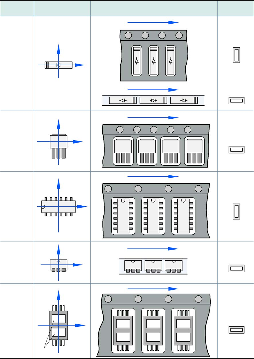
5.9.3 Component coordinate system and pick-up angle
5
Fig. 5.9 - 1 Position of the component and its pick-up angle
Special
component
Stick
magazine:
Chip-
components
with polarity
0402
2220
The anode must be
aligned with the +X
coordinate.
Package form Coordinate system
Position in the feeder module
Pick-up angle/
nozzle angle
Tape:
SOT 23
Stick
magazine:
Tape:
Tape:
SO-IC
DIL-IC
SOT 194
Tape:
Holes
Y
X
Y
X
Y
X
Y
X
Y
X
90°
90°
0°
90°
-90°
0°

User Manual SIPLACE X-Series 5 Tasks for the operating personnel
From software version SR.605.xx 07/2008 EN Edition 5.10 Refilling components
357
5.10 Refilling components
The online help contains information on refilling components with and without barcodes.
→ With tape feeder modules, make sure that you always splice on a new tape early enough so
that the feeder modules do not run out of components.
→ However, do not splice the tapes too early because if you wind the tape onto the new reel
after splicing the end of the old tape, the reel with the new tape may be overfilled. The tape
could then slip off the reel and become tangled. Under certain circumstances, this could
cause pick-up errors and prolonged down times.
→ Always insert spindles when using tape reels of 15" (381 mm) and larger (see Fig. 5.5 - 5
,
page 337
) and make sure that the separating plates are inserted correctly (see Fig. 5.5 - 4,
page 336
).
5 Tasks for the operating personnel User Manual SIPLACE X-Series
5.11 Docking the component trolley in or out From software version SR.605.xx 07/2008 EN Edition
358
5.11 Docking the component trolley in or out
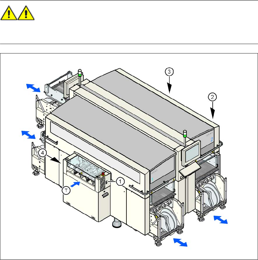
5.11.1 Safety instructions for docking component trolleys in and out
WARNING 5
To prevent accidents (risk of crushing), the component trolley may only be docked in or out by
one person.
5
Fig. 5.11 - 1 Safety instructions for docking the component trolley in or out
(1) Button for docking the component trolley in or out, location 1
(2) Button for docking the component trolley in or out, location 2
(3) Button for docking the component trolley in or out, location 3
(4) Button for docking the component trolley in or out, location 4
(T) Direction of PCB transport