00195722-0102_UM_X-Serie_SR605_EN.pdf - 第137页
User Manual SIPLACE X-Series 3 Technical data for the machine From software version SR.605.xx 07/2008 EN Edition 3.6 Gantry system 137 3.6.1.2 Position of the gantries for the X3 plac ement machine 3 Fig. 3.6 - 2 Positio…
3 Technical data for the machine User Manual SIPLACE X-Series
3.6 Gantry system From software version SR.605.xx 07/2008 EN Edition
136
3.6 Gantry system
3.6.1 Position of the gantries
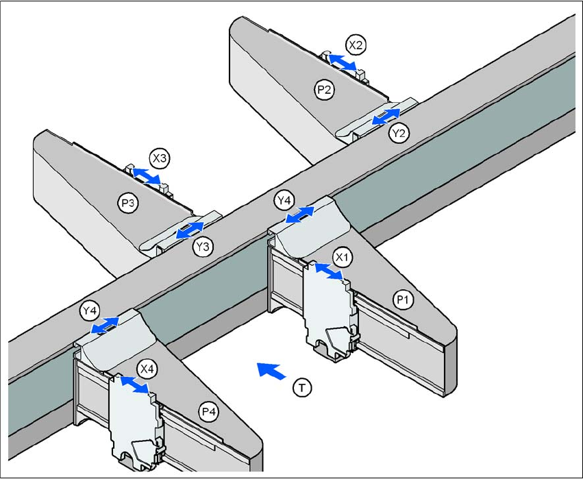
3.6.1.1 Position of the gantries for the X4 placement machine
3
Fig. 3.6 - 1 Position of the gantries for the X4 placement machine
P1, P2, P3, P4 (gantry 1, gantry 2, gantry 3, gantry 4)
X1 X axis, gantry 1
Y1 Y axis, gantry 1
X2 X axis, gantry 2
Y2 Y axis, gantry 2
X3 X axis, gantry 3
Y3 Y axis, gantry 3
X4 X axis, gantry 4
Y4 Y axis, gantry 4
(T) Direction of PCB transport
Placement area 2
Placement area 1
User Manual SIPLACE X-Series 3 Technical data for the machine
From software version SR.605.xx 07/2008 EN Edition 3.6 Gantry system
137
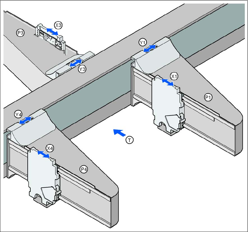
3.6.1.2 Position of the gantries for the X3 placement machine
3
Fig. 3.6 - 2 Position of the gantries for the X3 placement machine
P1 Gantry 1
X1 X axis, gantry 1
Y1 Y axis, gantry 1
P3 Gantry 3
X3 X axis, gantry 3
Y3 Y axis, gantry 3
P4 Gantry 4
X4 X axis, gantry 4
Y4 Y axis, gantry 4
(T) Direction of PCB transport
Placement area 2
Placement area 1
3 Technical data for the machine User Manual SIPLACE X-Series
3.6 Gantry system From software version SR.605.xx 07/2008 EN Edition
138
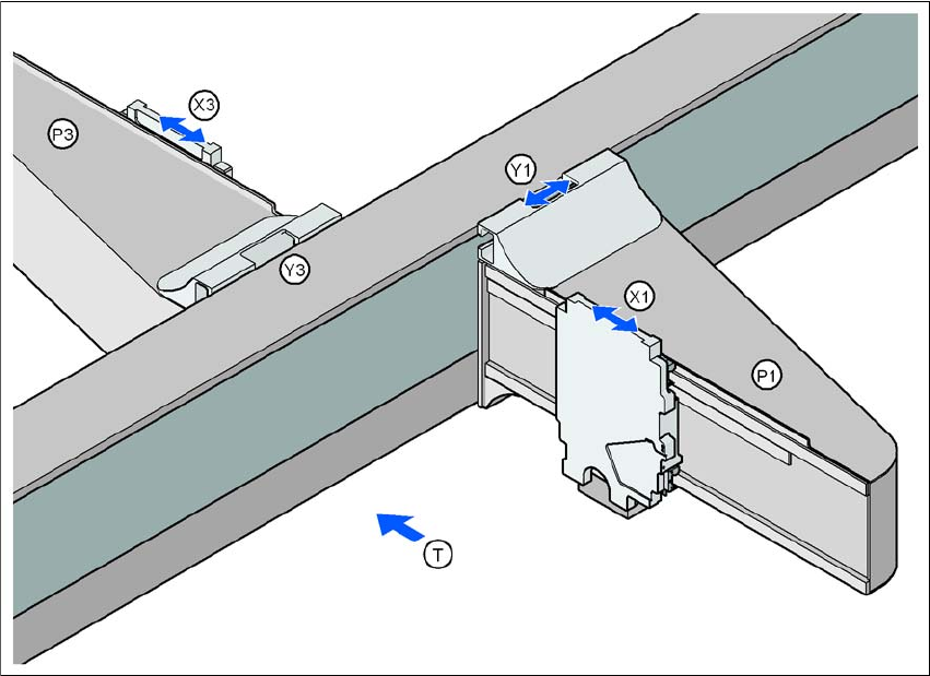
3.6.1.3 Position of the gantries for the X2 placement machine
3
Fig. 3.6 - 3 Position of the gantries for the X2 placement machine
P1 Gantry 1
X1 X axis, gantry 1
Y1 Y axis, gantry 1
P3 Gantry 3
X3 X axis, gantry 3
Y3 Y axis, gantry 3
(T) Direction of PCB transport
The gantry system consists of two functional groups
–X axis and
–Y axis
Placement area 2
Placement area 1