00195722-0102_UM_X-Serie_SR605_EN.pdf - 第231页
User Manual SIPLACE X-Series 3 Technical data for the machine From software version SR.605.xx 07/2008 EN Edition 3.12 SIPLACE HF component trolley 231 3.12.5.1 T ape reel diameter in relation to the PCB conveyor height 3…
3 Technical data for the machine User Manual SIPLACE X-Series
3.12 SIPLACE HF component trolley From software version SR.605.xx 07/2008 EN Edition
230
3.12.5 SIPLACE HF tape container
The tape container can hold reels up to 19" in diameter. The insertion of separating plates is de-
scribed in Section 5.5
on page 332.
PLEASE NOTE
For optimum operation, we recommend the use of spindles for 15" diameter or more.
3
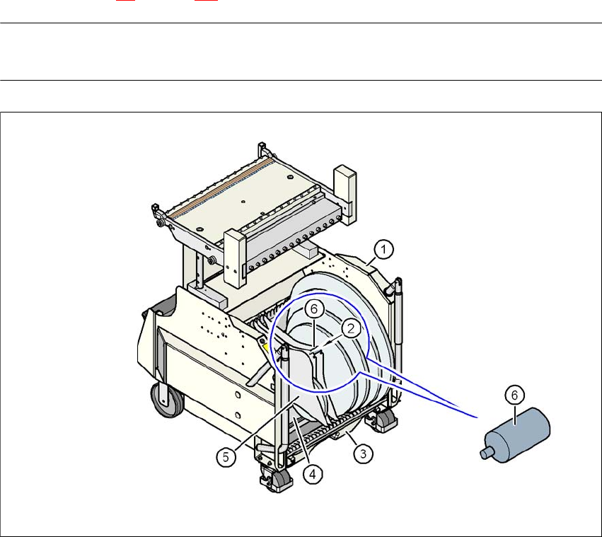
Fig. 3.12 - 5 SIPLACE HF component trolley with tape container
(1) Component trolley
(2) Position of the spindles
(3) Waste tape container
(4) Tape container
(5) Separating plate
(6) Spindle (enlarged)

User Manual SIPLACE X-Series 3 Technical data for the machine
From software version SR.605.xx 07/2008 EN Edition 3.12 SIPLACE HF component trolley
231
3.12.5.1 Tape reel diameter in relation to the PCB conveyor height
3
3.12.6 External power supply for the SIPLACE HF component trolley
Item no. 00119781-xx External power supply, component trolley, D1/D2/D3/X
To keep the time required for a setup change as short as possible, component trolleys can be set
up in advance at a special external location. The feeder module functions and setting can be
checked there to prepare for use. We provide an external power supply for this purpose. It is used
to supply the component trolley with the required electrical power and compressed air.
3.12.6.1 Technical data
The kit contains a main power cable to European standards, a main power cable to US standards
and a connecting cable between the power supply and the component trolley.
3.12.7 Compressed air supply for bulk case feeder modules, SIPLACE HF
component trolley
Item no. 00142335-xx Bulk case compressed air distributor, component trolley,
SIPLACE HF/X/D3
Bulk case feeder modules require compressed air in order to work. A compressed air supply for
bulk case feeder modules is therefore available as an option.
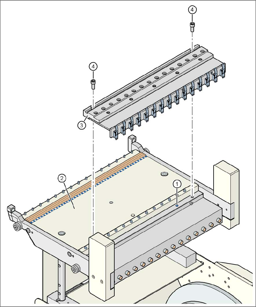
It is easy to fit. First remove the sealing plug (item 1) from the compressed air connection on the
component table (item 2). Then use two screws DIN 912, M8x20 (item 4) to fix the compressed
air supply (item 3) to the component table (item 2). The compressed air supply has retaining clips
(item 5) on the back. They fix the bulk case feeder modules to the component table and thus en-
sure a perfect compressed air supply.
Option –
With support for 3rd tape
reel
PCB conveyor height
of the component trolley
Tape reel diameter Tape reel diameter
830 mm 17" 15"
900 mm 19" 17"
930 mm 19" 17"
950 mm 19" 19"
Main power voltage 230 VAC ± 5%
120 VAC ± 5%
Compressed air connection Max. 1.0 MPa (10 bar)
Output pressure Can be regulated with a valve
3 Technical data for the machine User Manual SIPLACE X-Series
3.12 SIPLACE HF component trolley From software version SR.605.xx 07/2008 EN Edition
232
3
Fig. 3.12 - 6 Compressed air supply for bulk case feeder modules, SIPLACE HF component trolley
(1) Sealing plug on the component table
(2) Component table
(3) Compressed air supply for bulk case feeder modules
(4) Screw DIN 912, M8x20
(5) Retaining clamp