00195722-0102_UM_X-Serie_SR605_EN.pdf - 第332页
5 Tasks for the operating personnel User Manual SIPLACE X-Series 5.5 Carrying out a walk-through inspection Fr om software version SR.605.xx 07/2008 EN Edition 332 5.5 Carrying out a walk-through inspection 5.5.1 Checkin…
User Manual SIPLACE X-Series 5 Tasks for the operating personnel
From software version SR.605.xx 07/2008 EN Edition 5.4 Changing shift
331
5.4.2 Safety instructions for emptying the waste tape container
5
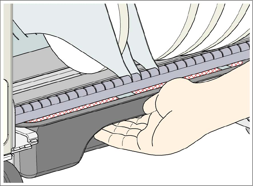
Fig. 5.4 - 1 Safety instructions for emptying the waste tape container
The waste tape container must be pulled out of the component trolley for emptying. There is a risk
of catching your thumbs as you do so.
→ To avoid this risk, hold the waste tape container with your fingers on the underside of the han-
dle and place your thumb on the handle.
→ Do NOT put your thumbs in the gap between the tape container and waste tape container as
you could catch your thumbs if you do.
5 Tasks for the operating personnel User Manual SIPLACE X-Series
5.5 Carrying out a walk-through inspection From software version SR.605.xx 07/2008 EN Edition
332
5.5 Carrying out a walk-through inspection
5.5.1 Checking the X feeder modules
5
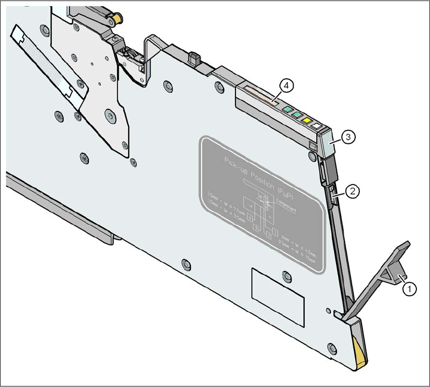
Fig. 5.5 - 1 Checking the X feeder modules
(1) Flap
(2) Blade
(3) Status display
(4) LCD display
5
→ Check to see whether the tape foil removal container for the X tape feeder module is full.
Open the flap (item 1). Pull out the cover foil and cut it with scissors or on the integral blade
(item 2) on 8 and 12 mm X tape feeder modules.
User Manual SIPLACE X-Series 5 Tasks for the operating personnel
From software version SR.605.xx 07/2008 EN Edition 5.5 Carrying out a walk-through inspection
333
PLEASE NOTE 5
Never tear the cover foil. This can cause problems with the cover foil pull-off. There is an in-
tegral blade (item 2) for easily cutting the on the 8 and 12 mm X tape feeder modules.
→ Check the multicolor status display (item 3 in Fig. 5.5 - 1
, page 332).
– If it lights up green, the feeder module is on standby.
– If it lights up orange, it is signaling a warning. The text of the warning appears on the LCD
display (item 4 in Fig. 5.5 - 1
, page 332).
– If the status display lights up red, a malfunction has occurred. The text of the warning
appears on the LCD display (item 3 in Fig. 5.5 - 1
, page 332).
A list of the LCD and status displays on the operator panel is given in Section 5.7
, page
351
. 5
If the status display is off, the cause may be as follows: 5
– The feeder module is not in the current set-up.
– The feeder module is defective.
– The feeder module has been disabled (due to a drop in pressure, for example)
5.5.2 Checking the S feeder modules
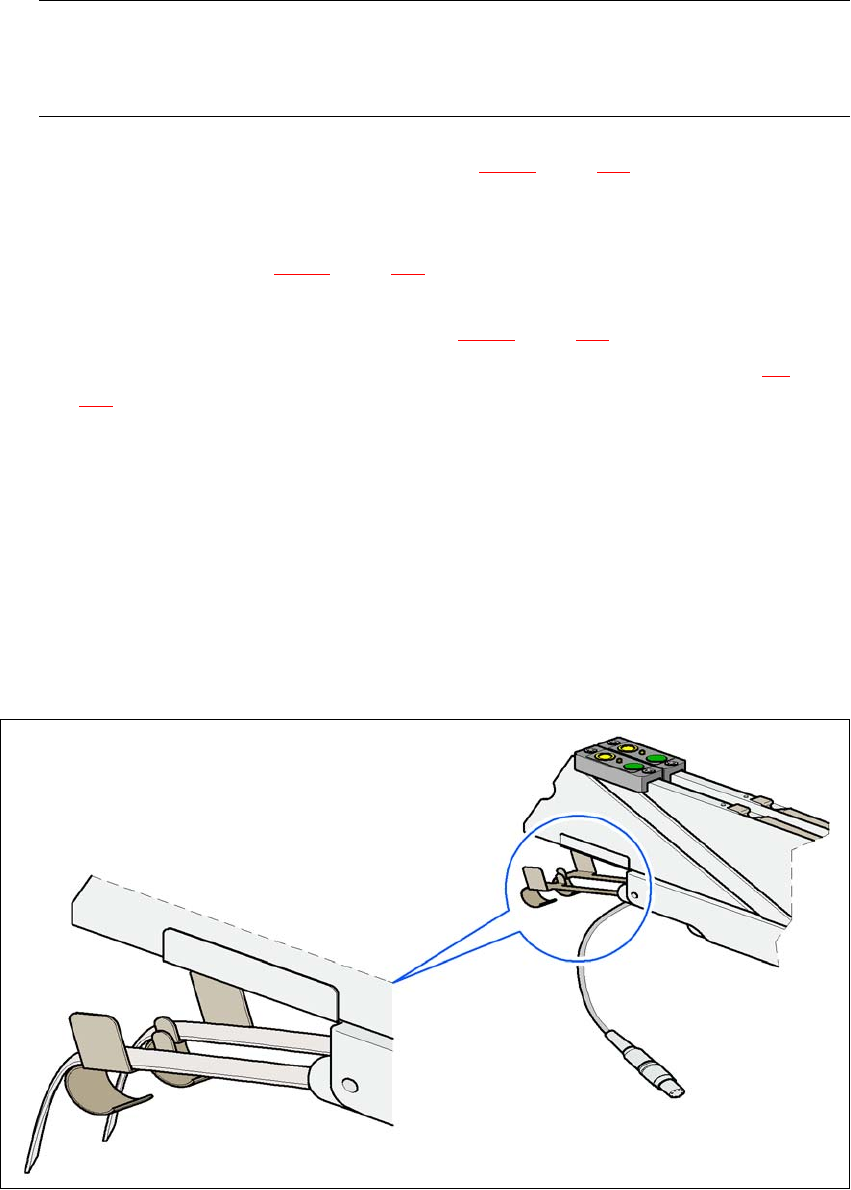
→ Make sure that the tape is correctly placed in the springs of the S feeder module.
5
Fig. 5.5 - 2 Placing the tape in the springs of the S feeder module