00195722-0102_UM_X-Serie_SR605_EN.pdf - 第70页
2 Operational safety User Manual SIPLACE X-Series 2.5 Safety instructions for operating the machine From software version SR.605.xx 07/2008 EN Edition 70 2.5.7 Note on the ESD safety of the placement machines Only use no…
User Manual SIPLACE X-Series 2 Operational safety
From software version SR.605.xx 07/2008 EN Edition 2.5 Safety instructions for operating the machine
69
2.5.6 Safety instructions for docking the component trolley in or out
WARNING
To prevent accidents (risk of crushing), the component trolley may only be docked in or out by
one person.
2
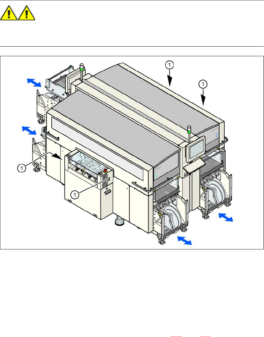
Fig. 2.5 - 5 Buttons on the input and output side for docking the component trolley in or out
2
(1) Buttons on the input and output side for docking the component trolley in or out
2
The safety concept for the component trolley change requires the operator to press a button (item
1) on the input or output side of the machine in order to dock the component trolley in or out. This
ensures that the operator is always standing to the side of the placement machine. In addition, the
component trolley can only be docked in if the protective covers are closed.
Docking the component trolley in or out is described in Section 5.11
, page 358. Follow the instruc-
tions exactly as described in this section.

2 Operational safety User Manual SIPLACE X-Series
2.5 Safety instructions for operating the machine From software version SR.605.xx 07/2008 EN Edition
70
2.5.7 Note on the ESD safety of the placement machines
Only use nozzles that are identified as conductive. This is the only way to meet the requirements
for the ESD safety of the machine.
2.5.8 Safety instructions for emptying the waste tape container
The waste tape container must be pulled out of the component trolley for emptying. There is a risk
of catching your thumbs as you do so. Please observe the safety instructions given in Section
5.4.2
, page 331 to prevent this from happening.
2.5.9 Safety instructions for correct use of the reject bin
Observe the following instructions to avoid risk of collision between the placement head and com-
ponent or the nozzle reject bin:
→ Make sure, that the reject bin is seated correctly in its mount.
→ Check that the reject bin does not project over the mount.
PLEASE NOTE 2
For every reject bin, a sensor (see Section 6.5
, page 431) can be retrofitted which signalizes the
correct position of the reject bin.
User Manual SIPLACE X-Series 2 Operational safety
From software version SR.605.xx 07/2008 EN Edition 2.5 Safety instructions for operating the machine
71
2.5.10 High temperatures at the C&P20A placement head during continuous oper-
ation
2
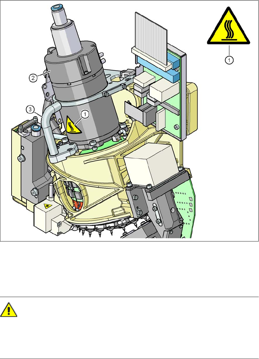
Fig. 2.5 - 6 High temperatures at the C&P20A placement head during continuous operation
(1) Temperature information plate, item no. 03031926-01
(2) Housing for the star motor
(3) Handle
CAUTION
HIGH TEMPERATURES 2
The housing of the star motor and the handle on the placement head may become very hot dur-
ing continuous operation and in ambient temperature in excess of 22 °C. Be careful when touch-
ing the parts.