00195722-0102_UM_X-Serie_SR605_EN.pdf - 第229页
User Manual SIPLACE X-Series 3 Technical data for the machine From software version SR.605.xx 07/2008 EN Edition 3.12 SIPLACE HF component trolley 229 3.12.4 Dimensions and center of gravity of the SIPLACE HF component t…
3 Technical data for the machine User Manual SIPLACE X-Series
3.12 SIPLACE HF component trolley From software version SR.605.xx 07/2008 EN Edition
228
The interface for the power module, communication and safety circuits is beneath the component
table bed (item 6 in Fig. 3.12 - 3
, page 227). The compressed air supply for bulk case feeder mod-
ules also passes via this interface.
PLEASE NOTE
All component trolleys, matrix tray changers or waffle-pack changers must be docked on the
machine in order to operate it. If they are not, the machine stays in EMERGENCY STOP status.
The placement process is interrupted.
The communication interface (item 3 in Fig. 3.12 - 3
, page 227) supplies the necessary voltages
and control signals to the feeder modules.
In the standard version, the tape reel container (item 4 in Fig. 3.12 - 3
, page 227) holds tape reels
up to 17" (432 mm). The pull-out waste tape container (item 5 in Fig. 3.12 - 3
, page 227) can be
found beneath the chassis. The cut waste tape travel down a chute into the waste tape container,
which must be regularly emptied.
CAUTION 3
Follow the safety instructions in Section 5.4.2
, page 331, when you pull the waste tape container
out of the component trolley.
3.12.3 Technical data
3
3
Length x width
Height (see Fig. 3.12 - 4
, page 229)
727 x 592 mm²
752 x 592 mm² with waste tape container
830 mm for 830 mm PCB conveyor height
900 mm for 900 mm PCB conveyor height
930 mm for 930 mm PCB conveyor height
950 mm for 950 mm PCB conveyor height
PCB conveyor height 830 mm ± 15 mm (standard)
900 mm ± 15 mm (option)
930 mm ± 15 mm (option)
950 mm ± 15 mm (SMEMA option)
Weight
Without feeder modules
With feeder module at all locations
88.9 kg
143.7 kg
Reel diameter
Standard
Maximum
Up to 432 mm (17")
483 mm (19")
Feeder module locations max. 15
User Manual SIPLACE X-Series 3 Technical data for the machine
From software version SR.605.xx 07/2008 EN Edition 3.12 SIPLACE HF component trolley
229
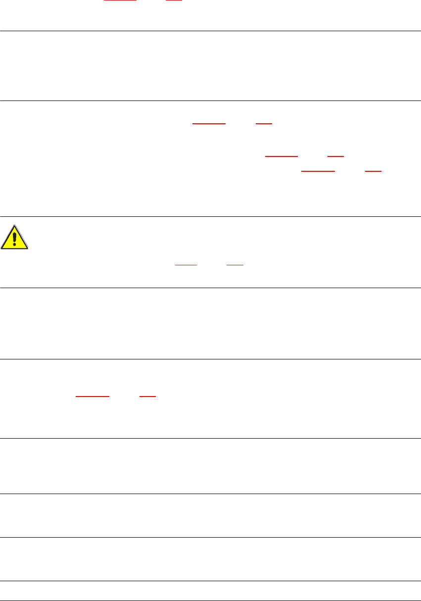
3.12.4 Dimensions and center of gravity of the SIPLACE HF component trolley
3
Fig. 3.12 - 4 Dimensions of the component trolley, SIPLACE HF, all dimensions in millimeters
3
The center of gravity (A) of the component trolley was determined for a PCB conveyor height of
830 mm.
3 Technical data for the machine User Manual SIPLACE X-Series
3.12 SIPLACE HF component trolley From software version SR.605.xx 07/2008 EN Edition
230
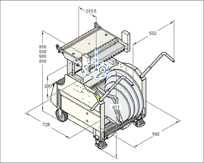
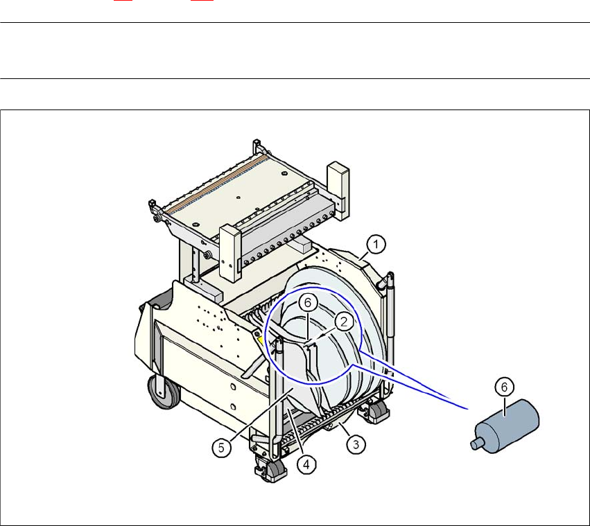
3.12.5 SIPLACE HF tape container
The tape container can hold reels up to 19" in diameter. The insertion of separating plates is de-
scribed in Section 5.5
on page 332.
PLEASE NOTE
For optimum operation, we recommend the use of spindles for 15" diameter or more.
3
Fig. 3.12 - 5 SIPLACE HF component trolley with tape container
(1) Component trolley
(2) Position of the spindles
(3) Waste tape container
(4) Tape container
(5) Separating plate
(6) Spindle (enlarged)