00195722-0102_UM_X-Serie_SR605_EN.pdf - 第453页
User Manual SIPLACE X-Series 6 Station extensions From software version SR.605.xx 07/2008 EN Edition 6.18 Coplanarity la ser module 453 The T winHead picks up the component to be checked, ce nters it optically using the …
6 Station extensions User Manual SIPLACE X-Series
6.18 Coplanarity laser module From software version SR.605.xx 07/2008 EN Edition
452
NEVER look directly into the laser beam, despite the low laser output. The beam is visible, so the
eyes will be protected by the natural eyelid-closing reflex.
WARNING 6
Only authorized personnel may open the housing of the optical sensor.
For repair and servicing, always return the sensors to SIPLACE.
6.18.2 Description
The coplanarity laser module is used to measure vertical bending of the leads. The lead length is
measured without contact using the laser triangulation principle.
6
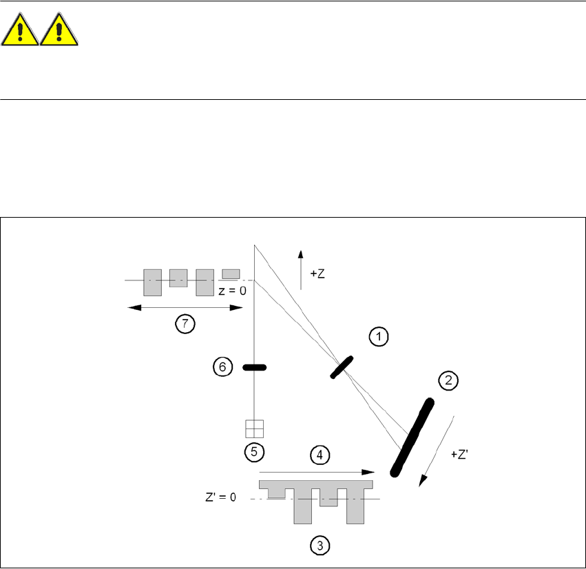
Fig. 6.18 - 2 Laser triangulation measurement principle
(1) Receiver lens
(2) Detector
(3) Measuring signal
(4) Time t
(5) Laser
(6) Transmitter lens
(7) Travel direction

User Manual SIPLACE X-Series 6 Station extensions
From software version SR.605.xx 07/2008 EN Edition 6.18 Coplanarity laser module
453
The TwinHead picks up the component to be checked, centers it optically using the component
vision camera (see Section 6.7
, page 432) and moves all four sides one after another over the
fixed laser beam of the coplanarity laser module. In this way, every lead is scanned from below by
the laser beam. The laser light scattered by the underside of the lead is recorded by a sensor, and
is then used to calculate the exact position of the lead with respect to the PCB. The position values
thus calculated are compared against the limit value specified by the user. If they exceed this
value, the component is disposed of or returned.
The coplanarity laser module is used in combination with the optical component centering mode.
Components with bent or missing leads are detected and disposed of, if necessary.
6.18.3 Technical data
6
6.18.4 Restrictions
– The component must have a minimum of two and a maximum of four rows of gull-wing leads.
– The row of leads should be located orthogonally to each other.
– The leads should be trained orthogonally to the row of leads.
– The ends of the leads lie on a straight line.
– Measurement of components with just one row of leads is not possible.
Components Gullwing
Accuracy ± 18.5 µm (3σ) (reference component)
± 24.7 µm (4σ)
± 30.5 µm (3σ) (components up to 32 mm)
± 40.7 µm (4σ)
± 31.3 µm (3σ) (components up to 55 mm)
± 41.7 µm (4σ)
Max. component size 55 x 55 mm²
Min. lead pitch 300 µm
Max. CO height 25 mm
Positioning option Location 3 on SIPLACE X2 and X3, alternative to the 3D coplanarity
laser module
Placement head type TwinHead
6 Station extensions User Manual SIPLACE X-Series
6.18 Coplanarity laser module From software version SR.605.xx 07/2008 EN Edition
454
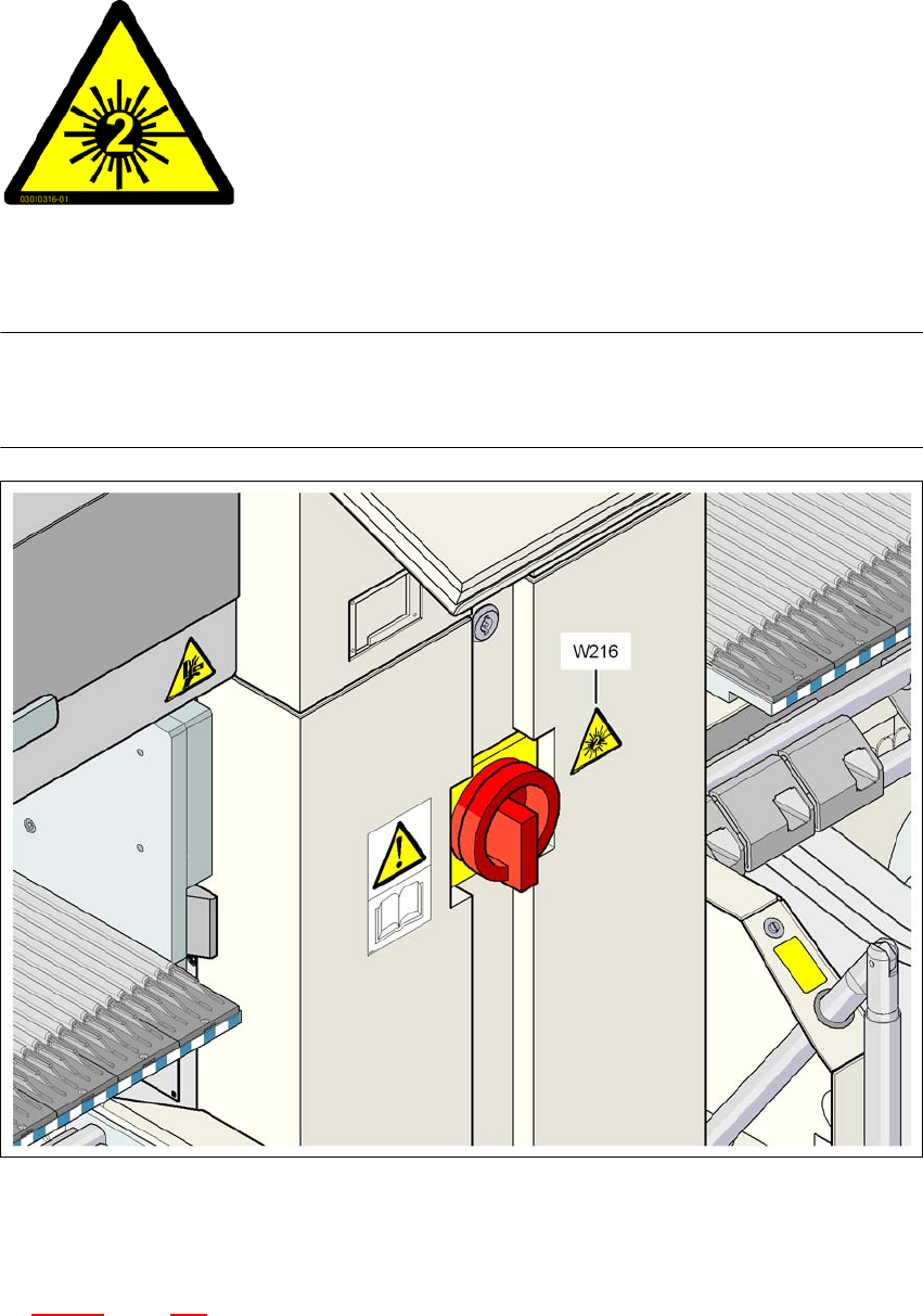
6.18.5 Identify machine with warning label
6
Warning label W216 "Laser class 2" on the cover beside the main switch,
item no. 03010316-01 (number per placement machine: 1)
PLEASE NOTE 6
When the coplanarity laser module is fitted, the placement machine must be classified as laser
class 2. The laser module is not integrated into the EMERGENCY STOP circuit.
6
Fig. 6.18 - 3 Warning label W216 beside the main switch
→ Identify the machine with warning sign W216 "Laser class 2", item no. 03010316-xx.
→ Stick warning label W216 beside the main power switch on the cover (see item W216 in Fig.
6.18 - 3
, page 454).
6
6
6
6
6
6
LASER RADIATION!
Do not look into beam
Laser class 2