00195722-0102_UM_X-Serie_SR605_EN.pdf - 第466页
6 Station extensions User Manual SIPLACE X-Series 6.22 SIPLACE X-series Productivity Shuttle (XPS) Fr om software version SR.605.xx 07/2008 EN Edition 466 6.22 SIPLACE X-series Productivity Shuttle (XPS) Item no. 001 199…
User Manual SIPLACE X-Series 6 Station extensions
From software version SR.605.xx 07/2008 EN Edition 6.21 SIPLACE X-series Productivity Lane (XPL)
465
The "SIPLACE X-series Productivity Lane" option
a
in the middle of the PCB conveyor allows
PCBs to be overtaken in the placement machine. As with the Productivity Lift, the placement ma-
chine is operated in parallel. This third conveyor track can be viewed from above, and even works
with the protective cover open. This allows the path that the PCB takes through the machine to be
followed for checking purposes. SIPLACE X-series Productivity Shuttles (see Section 6.22
, page
466
) on the input/output side of the machine or line distribute the PCBs to be processed to the
required track of the PCB conveyor or to the third conveyor track.
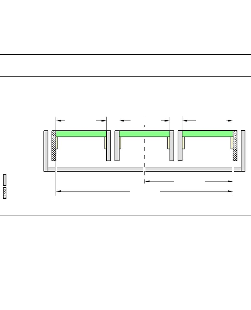
6.21.3 PCB widths
6
6
Fig. 6.21 - 2 Maximum PCB widths - conveyor edges 535 mm stationary, SIPLACE XP
a) See "SIPLACE X-series Productivity Lane" manual
Conveyor mode PCB width
track 1
PCB width
SIPLACE XPL
PCB width
track 2
XPL max. 154 mm max. 154 mm max. 154 mm
6
max. 154 mm
6
max. 154 mm
6
267.5 mm
6
535 mm
6
Movable
conveyor edge
6
Stationary
conveyor edge
6
max. 154 mm
6 Station extensions User Manual SIPLACE X-Series
6.22 SIPLACE X-series Productivity Shuttle (XPS) From software version SR.605.xx 07/2008 EN Edition
466
6.22 SIPLACE X-series Productivity Shuttle (XPS)
Item no. 00119972-xx SIPLACE X-series Productivity Shuttle
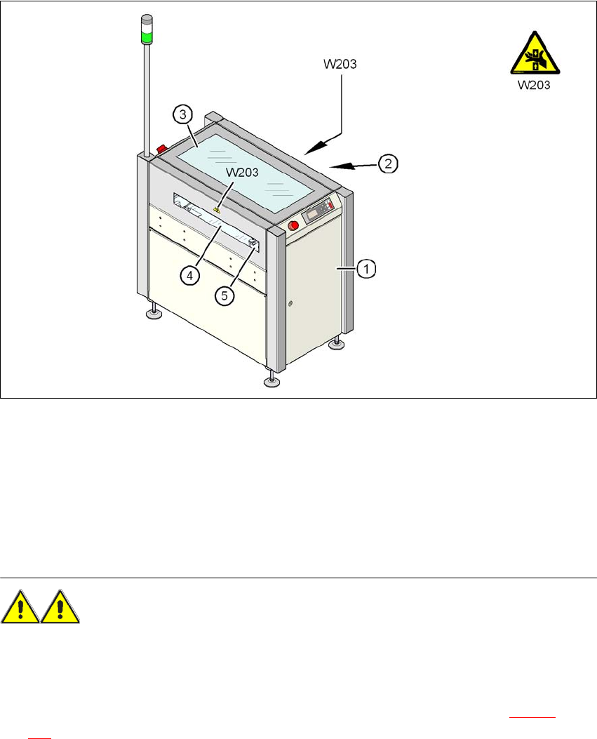
6.22.1 Safety instructions
6
Fig. 6.22 - 1 Risk of crushing on the input and output side of the SIPLACE X-series Productivity Shuttle
(1) X-series Productivity Shuttle
(2) Output side
(3) Cover
(4) Input side
(5) Part of the conveyor belt
WARNING
RISK OF CRUSHING HANDS
– The safety measures to be taken on the input / output side and at the cover flap of the XPS
are the responsibility of the customer.
– The openings for the conveyor on the input and output sides (item 2 or 4 in Fig. 6.22 - 1
, page
466
) are large enough to allow the entire conveyor belt width of the shuttle to be used. During

User Manual SIPLACE X-Series 6 Station extensions
From software version SR.605.xx 07/2008 EN Edition 6.22 SIPLACE X-series Productivity Shuttle (XPS)
467
operation there is a risk that operators can catch their fingers if they reach into the openings
on the input or output side.
– Asys can therefore supply an optional cover that is designed for the conveyor belt.
– If the shuttle is linked to a SIPLACE machine or installed between two SIPLACE machines,
there is again a risk of crushing for the operator while the conveyor belts are in use. If the
cover flap is open on the input or output side of the SIPLACE machines, the operator can
reach through to the shuttle.
→ Fix the Eslon bracket supplied (see item 3 in Fig. 6.22 - 1
, page 466) to the cover of the shut-
tle.
6.22.2 Description
The SIPLACE X-series Productivity Shuttle
a
moves PCBs from one to three incoming conveyor
tracks to up to three outgoing conveyor tracks. The virtual PCB panel coming in on a conveyor
track is transferred to an outgoing conveyor section. The separation function for PCBs on the shut-
tle can be set as required, and supplies the SIPLACE placement machine with the combined
PCBs.
a) See the "SIPLACE X-series Productivity Shuttle" user manual