00195722-0102_UM_X-Serie_SR605_EN.pdf - 第62页
2 Operational safety User Manual SIPLACE X-Series 2.3 Laser classification Fr om software version SR.605.xx 07/2008 EN Edition 62 2.3 Laser classification 2.3.1 Laser class 1 2.3.1.1 Classification of the whole mac hine …
User Manual SIPLACE X-Series 2 Operational safety
From software version SR.605.xx 07/2008 EN Edition 2.2 Warning labels
61
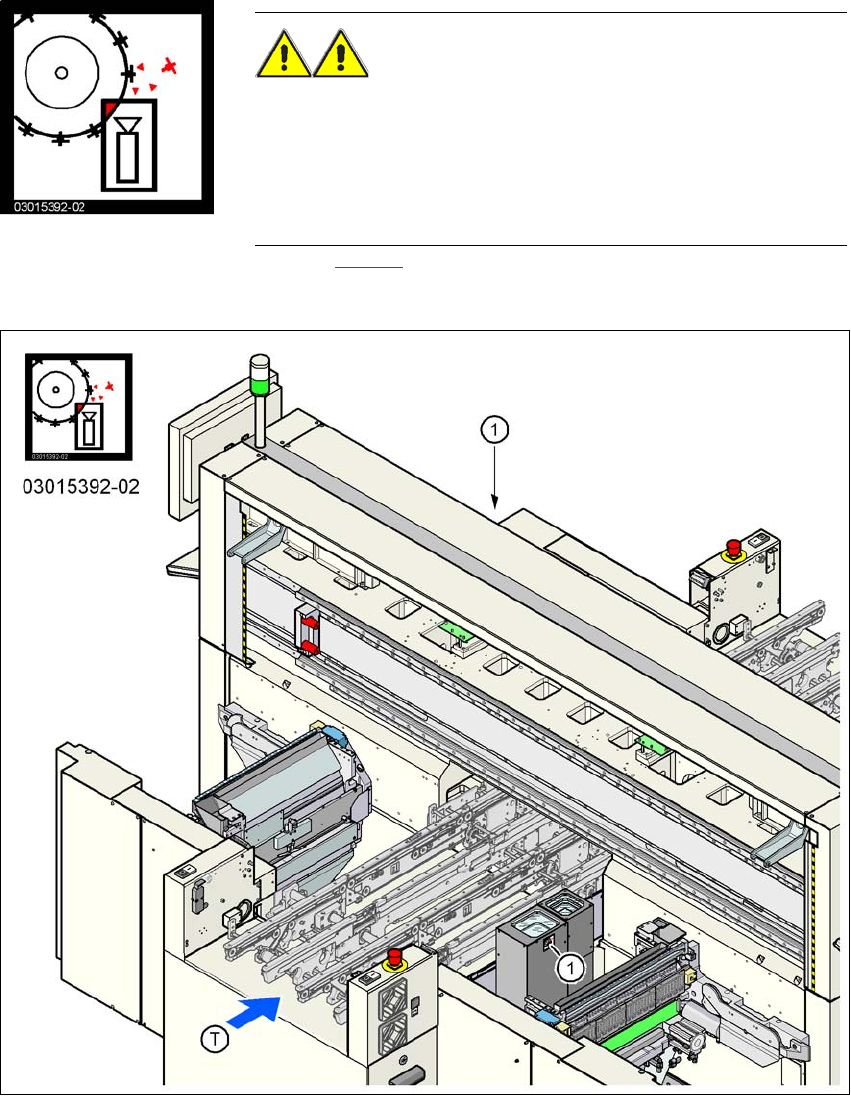
2.2.8 "Head crash" information plate on the IC camera of the TwinHead
"Head crash" information plate in Fig. 2.2 - 17, item no. 03015392-02
(number per placement machine: maximum 4)
2
Fig. 2.2 - 17 "Head crash" information plate on the IC camera of the TwinHead
(1) "Head crash" information plate on the IC camera of the TwinHead
WARNING RISK OF HEAD CRASH 2
When the placement head is changed from the TwinHead to the
Collect&Place head, the TwinHead's component cameras (station-
ary, P&P, type 33, 55 x 45, and type 25, 16 x 16) must be removed,
otherwise the Collect&Place head will collide with the camera hous-
ings.
2 Operational safety User Manual SIPLACE X-Series
2.3 Laser classification From software version SR.605.xx 07/2008 EN Edition
62
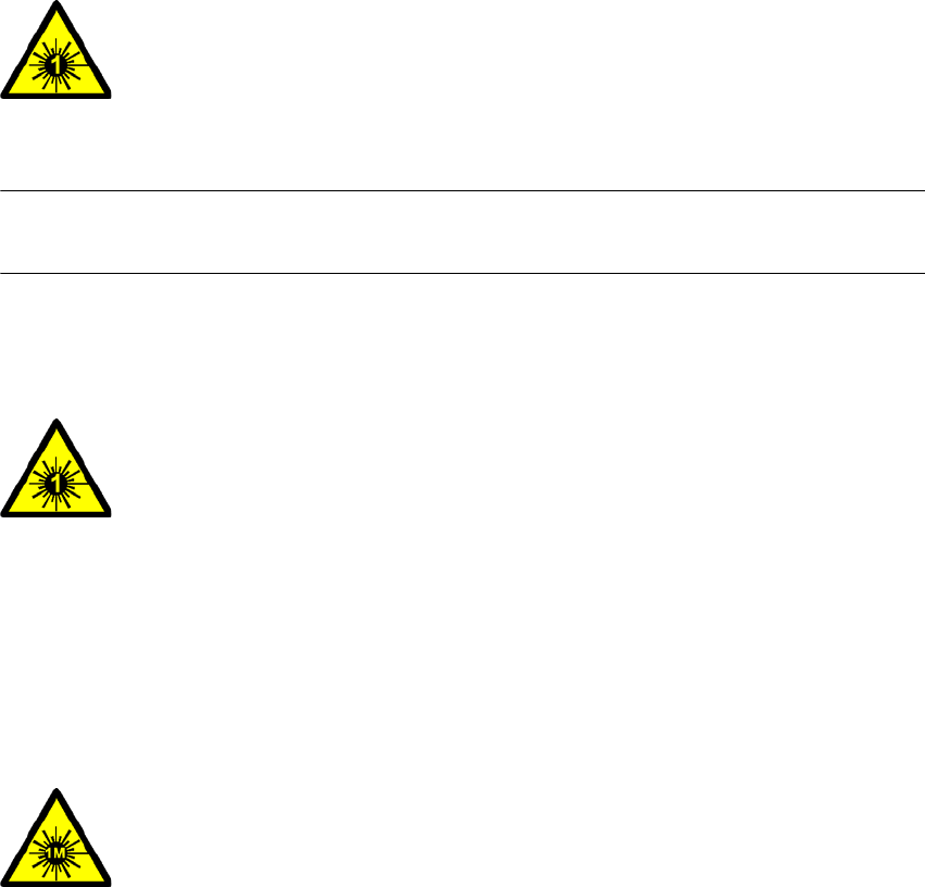
2.3 Laser classification
2.3.1 Laser class 1
2.3.1.1 Classification of the whole machine
2
PLEASE NOTE: 2
Modules in laser classes 1 and 1M are not identified.
2.3.1.2 Classification of the camera systems
2
2.3.2 Laser class 1M
Do not look directly at this with optical instruments!
2
2
All installed camera systems and the whole machine when ready
for operation are assigned to laser class 1.
The laser classes are determined according to DIN EN 60825-
1:2001.
2
The following camera systems are assigned to laser class 1:
– Component cameras for the SIPLACE TwinHead
Stationary P&P component camera, type 33, 55 x 45, digital
Stationary P&P component camera, type 25, 16 x 16, digital
2
The following camera systems are assigned to laser class 1M:
– C&P CO camera, type 23, 6 x 6 on the 20-segment Collect&Place head
– C&P CO camera, type 28, 18 x 18 on the 12-segment Collect&Place head
– C&P CO camera, type 29, 27 x 27 on the 12-segment Collect&Place head
– C&P CO camera , type 29, 27 x 27 on the 6-segment Collect&Place head
User Manual SIPLACE X-Series 2 Operational safety
From software version SR.605.xx 07/2008 EN Edition 2.4 Safety instructions for transporting the machine
63
2.3.3 Laser class 2
The following modules are assigned to laser class 2:
– Laser light barrier, placement area 1 in the PCB conveyor
– Laser light barrier, placement area 2 in the PCB conveyor
– PCB barcode scanner
– Component sensor on the 20-segment Collect&Place head
– Coplanarity laser module
– 3D coplanarity laser module
(The entire machine is classified as laser class 2 if the coplanarity laser module option is installed.)
2
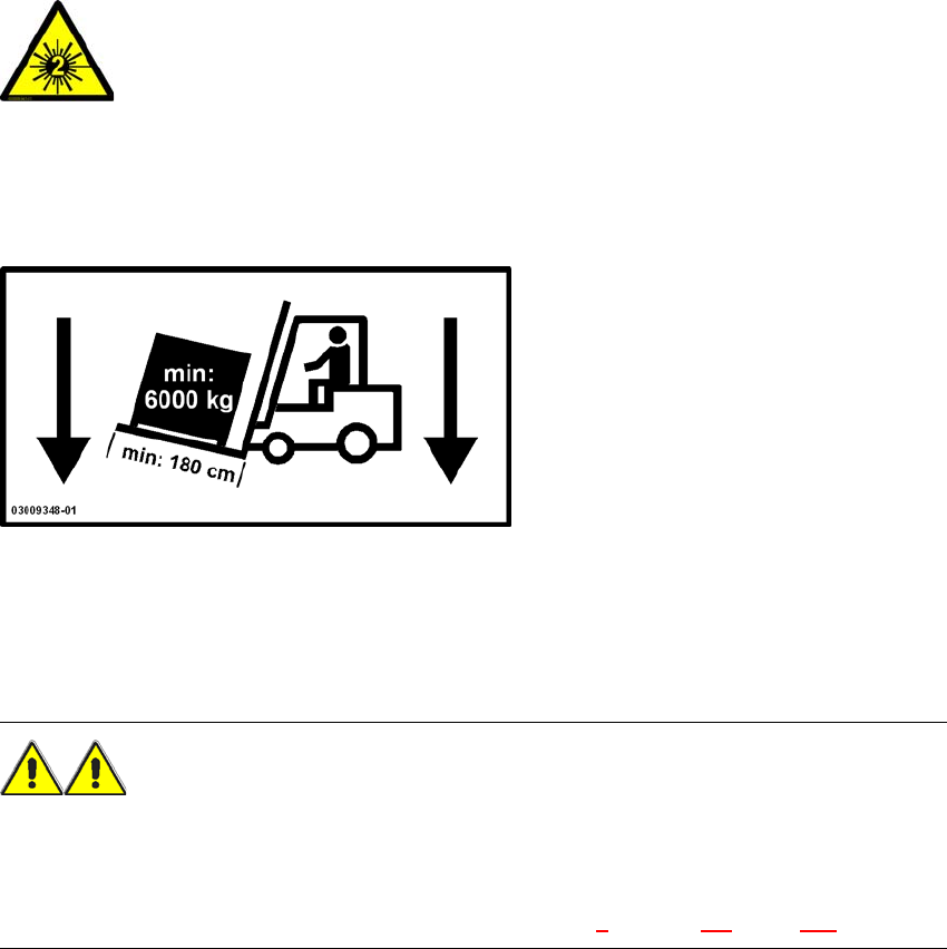
2.4 Safety instructions for transporting the machine
2
Use a fork-lift truck with the following specification to carry the machine:
Fork length: min. 1800 mm
Carrying power: min. 6000 kg
Clear width between forks: min. 350 mm 2
WARNING
RISK OF TIPPING 2
If the required specification cannot be applied to the fork-lift, there is a risk that the fork-lift will tip
over when carrying the placement machine.
Transporting the placement machine is described in chapter 4, Section 4.1, page 237.
2
Laser radiation
Do not look into beam!